After building and finishing the two
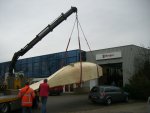
floats, now it's the turn for
the main hull. Please click on the images to open an extensive photo gallery of
the various stages in the building process.
Beam Bulkheads:
Before setting up the main hull, and while still having the room, I first made the beam bulkheads as these
requires a special construction for the folding mechanism. A rather big
laminating job with vacuum bagging. The first attempt is a bit disappointing,
with epoxy everywhere, not only on the part, but also everywhere else. Because
of a too sharp edge on the molded flange I pulled a big hole in the underside of
the vacuum bag. Getting a wet vacuum bag airtight again is quite a job. While
the resin clock continued it ended in a big mess. I left the workshop in my
underpants, and with epoxy in my hair (it's shorter now). Now I know again why I dislike vacuum bagging and like the vacuum
infusion so much. However, vacuum
bagging is the way to go for this complicated laminating job. Or just
hand-lay-up. But once used to the quality by a vacuum treatment, it's hard to be
content with anything less. I am very comfortable using it.
At the end, after eight vacuum bags, it's becoming
more of a routine with less mess and better vacuum bags. Practice, practice
..........
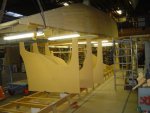
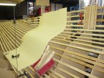
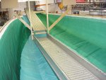
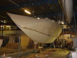
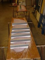
Setup first main hull half: This is one of these
memorable stages. Not only the "real boatbuilding" work, at
least the fun part has just begun in this stage, but more memorable is
the fact that the hull fits in my small workshop as I had thought to myself.
It's a close fitting and a relief at the same time. I've started with the
starboard side of the main hull as the geometry of this hull half fits better
in my workshop.
I knew before that the height of the workshop is not enough to
join the two main hull halves, so the planning is to make the second hull half
and the joining to a complete boat in a bigger workshop somewhere else (still to
find that place). This will be temporary and the completing of the boat will be
again in my garage.
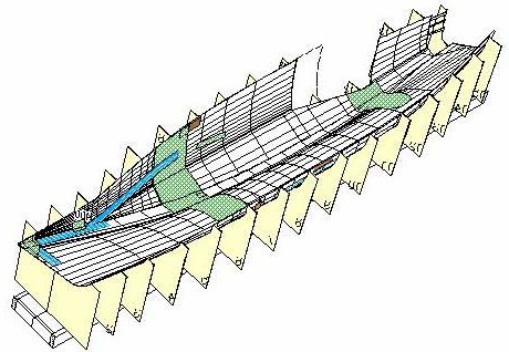
Layup dry laminate and infusion. The bag was perfect, the vacuum was
almost perfect, however after the vacuum was on, I discovered I had a batch of
wrong tubes. They look the same as I've had before, but these ones were pressed
together and useless for the infusion job. Very disappointing. As infusion was
planned for the next day (Monday, and with an announcement on the F-boat forum
for a live show on the webcam)) a quick ride to fellow builder Bert Hofman
brought the solution as he had enough tubes to help me out. It was late Sunday
evening (or better said Monday morning very early) when all tubes were replaced
by the good ones.
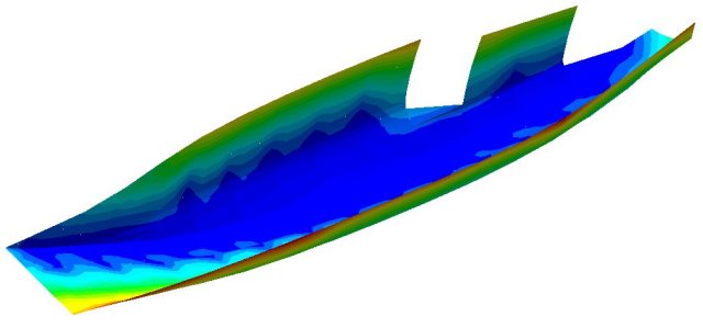
Below the video (14,6Mb) and at the right the moving animation (1 Mb) of the
infusion simulation.
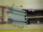
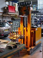
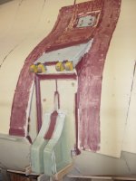
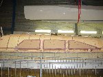
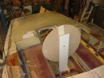
Beam bulkheads and folding system setup : Making and
positioning the carbon lower folding strut anchors turned out to be a tough job.
I've had some worries because they are such an important structural part of the
boat. The first two attempts were a bit disappointing but finally I developed
the right method to wrap the carbon around the anchors blanks.
The building project until now was mainly a matter of forming foam into hulls,
laminating (ok, better said infusing) and gluing bulkheads into position. It
gave me the feeling of putting a boat together, but not constructing something.
However, mounting the beam bulkheads and lower hull strut anchors with the
accompanying reinforcements is much different from that and gave me the feeling
of a constructing work. I was already impressed by the design drawings and
engineering quality of Ian Farrier and the way these elements are being
constructed is more than an confirmation of that.
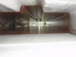
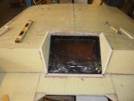
Daggerboard case:
The daggerboard case is made of marine plywood and I discovered the hard way
(at least after two failed vacuum bags) that the porosity of the plywood makes
it impossible to make an airtight seal with sealant tape onto the wood.
Something to remember for all wood builders. The vacuum infusion was done with
two bags, one for the infusion and one for the vacuum integrity. A stopgap and
not something to copy !
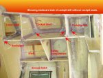
Bulkheads
and cockpit area. The finishing of this first main hull half with all the
structural bulkheads and the making of the cockpit coaming, emergency escape
hatch and the safety compartment.
On the left a video of the
infusion of the escape hatch coaming.
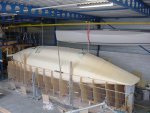
Unmolding
the starboard main hull half: This went on quite straight forward.
Turning the hull with the four tackles was exciting and she went over with literally just a couple of
millimeters to spare
Most of the work was cleaning up the mess and to find a new place for
all the stuff that I still don't want to throw away. The half hull is
remarkable stiff and instead of starting the other hull half I decided
to start with some more interior work as access to the hull is great in
this stage. However, life would be easier if I knew what do with
the interior ..... decisions, decisions .........
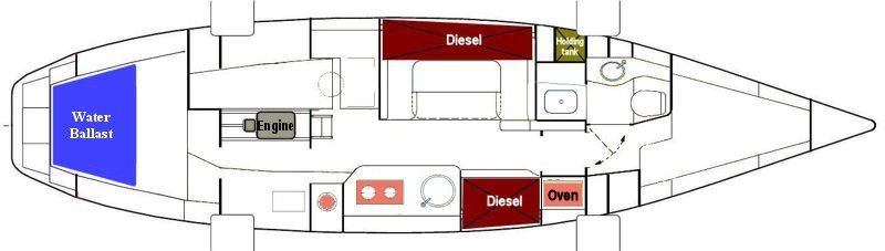
Interior layout: I finally decided about the layout of the interior. The
biggest change compared to the
standard aft cabin layout is the galley on
starboard instead of port. Main reason for this is that I still like "the
office" on board, which lead to a rather conventional layout, in particular in
combination with a quarter berth. Because of the galley on starboard the settee
in front of this is now shorter, but still useable as a (sea) bunk with the feet
through an opening in the cabin bulkhead. Above that the diesel oven is situated. Galley top
can be extended by folding down the backside of the settee back. The dinette is now two
meters wide and can be converted into a large spare double bunk. Also the shower
is a little wider. Without rebuilding the interior this can accommodate six (with
table down eight and with spare bunks in the floats even ten) Cooking is on a
ceramic diesel stove and in addition to this a fully gimbaled single
cylinder burner, positioned in a dedicated housing and well ventilated outside.
Of course the interior question is a matter of personal taste. I think this is a
good sea going layout and at least for now this design gives me some peace of
mind.
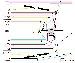
Systems: Click on the colored system items in the layout
drawing below to open a principle sketch about the subject. I will add more as
progress allows.
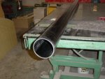
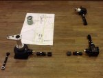
Carbon bobstay anchor:
Some time ago I had a look on the composite department of
Stork Aerospace
and there I learned that they put a lot of effort in saving weight at the ends
of airplanes and wings. Not a surprise of course but this reminded me of the
quite heavy bobstay anchor in the bow of the F39. In spite of the fact that I
prepared the piece of stainless steel to fasten into the bow, I decided to make
a much lighter carbon one, almost in the same way as the carbon chainplates.
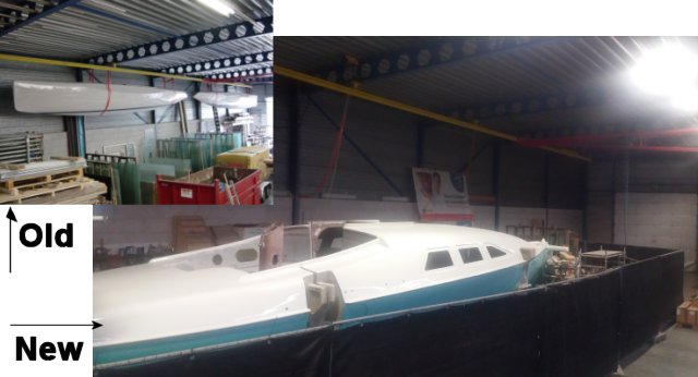
Moving to another workshop: Quite unexpected and totally on the spur of
the moment we bought a new house ..... Sometimes that one in a lifetime moment
comes along, in our case a water villa with a jetty large enough for mooring our
F-39 trimaran. So, the other "dream" we had, living in a
house near the water, has become a reality now and we will move to our new place
by the end of this year (2009). Which means I have to give up the workshop
at home and move the boatbuilding project to the workshop of our company.
This of course is a temporal solution with the necessity of getting in a hurry.
This means from now on I will focus on finishing the F39 on the outside and get
her in the water to tie her up along the jetty of our new home. Further work on
interior, hardware and rigging will be delayed till she is at home again.
Setup of the second main hull half. Again a fun
part to do. Working in the new workshop looks to be muich faster due to more
space, better equipment, less distraction and less socializing .....
And now there are a lot of critical observers (i.e. colleagues). N
o doubt
they will inspect the work on Monday morning to discuss the working rate of
their "boss" ..........
Boatbuilding
again. Fitting out the new workshop turned out to be much more time
consuming than anticipated. But now everything is in accordance with my wishes
and this weekend I had the feeling to continue the boatbuilding again instead of
all kind of other things, like organizing and cleaning up too much company
materials, dragging along too heavy girders, hoisting and mounting too heavy
winches, organizing and connecting too much electrical wires, building and
pulling down again an incomplete scaffolding, which despite some missing
components was strong enough to hold up the main hull half for a while, which by
the way wasn't necessary if I had done the electrical winches first, etc.
On
the left a video of the vertical foam stripping process and you can find
the photo's by clicking in the picture at the right.
Vacuum
infusion of second main hull half: The handling of all the glass and vacuum
materials is now much more convenient in this spacious workshop. However, in my
enthusiasm I forgot to add some reinforcements in the window area and the area
of the anchor locker. While writing this, the inside of the hull has been
covered with the vacuum materials except the vacuum bag. Next weekend I have to
fix that .......
On
one of the hottest days of the year (Saturday July 11 2010)
the vacuum infusion of the second main hull half went
flawlessly. I few hours before I was desperate not being
able to find a big leakage in the vacuum bag. At first I
thought having found the culprit, a forgotten connection of
a vacuum line. But after I repaired that nothing changed.
To be able to hear better, I put the vacuum pump outside the
building, however I knew that the leak was probably too big
to be able to hear. I spent the whole Friday evening and
Saturday morning on finding the leak. All kinds of scenarios
went through my mind, including the worst, a poreus or a
punctured hull. Just before I thought I was getting crazy, I
noticed the cleaning lady who was still in the building on
this Saturday morning. Knowing that women are much more
patient, I asked here to help me finding the leak. After 5
min (!?) she found a small leak in the bag. Unfortunately
nothing changed when I closed it with a piece of tacky tape.
Some minutes later she found the real wrongdoer, a big
square in the bag, hidden in a pleat. She made my day!
Thanks Angela! Now, I got some vacuum and the rest of the
leakages were easy to hear and I even finished with a
perfect bag.
The drop test (vacuum pump off) resulted
in a not worth mentioning loss of
vacuum. Room temperature was 32° Celcius
and so was the resin. Just perfect for a fast infusion. Click on the above
picture for the photo gallery and at the
right for the video of laying up the dry fabrics and infusion of this mainhull
half.
Port
side folding system setup and beam bulkheads: When working on the starboard
half I made all the carbon lower folding strut anchors, but not the complete
anchor assembly for this port side. So, before putting in these carbon anchors,
I first had to do some unfinished business on the carbon anchors. Cook them in
the oven (this time not the one in the kitchen) and making the total anchor
assembly.
Maybe it looks like I always have the things under control.
But that is only apparent and silly mistakes are indeed made.
After I freed
the two carbon anchor assemblies from their vacuum bag and
was preparing to mount the assembly in the hull, I
discovered that the base plate was shorter than the
anchor….. F**###(censored) In a fit of madness I had the
base plate mounted in the wrong direction. Itself is not so
bad were it not that all the UD fibers are now running in
the wrong direction. Too bad of all the beautiful laminate
work (and a waste of three days).
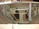
There is a lot of
laminating work to do around the beam bulkheads with up to
20 layers of UD fabric in some areas. This construction
looks to be real solid and bullet proof. As the lamination
and bond to surrounding areas is critical I try to be very
meticulous in this area.
A
milestone, Starboard meets port: Here some photo's of the joining of the two
main hull halves. Overall the hull halves fit very well together without
noticeable misalignment. On Menno's Blog (Dutch
F22 boat builder) I saw he used the two top battens to align both hull
halves. Great idea (thanks Menno) because these battens make the use of clamps
possible, which is much easier than bungling small wood pieces and screws.
I made the second (Port) main hull half a little longer in the stern. This was
not possible in my previous workshop due to the lack of space. After joining the
two halves I decided to make an extension to the Starboard half to make both
hull halves the same length. I don't know yet if I will make the hull one feet
longer, but doing this now in this stage is quite easy and I can always decide
afterwards to cut it off.
More bulkheads and details in the port side half:
I made all the other bulkheads in this port side after the joining of both hull
halves as aligning is much more easier this way. In the bow area I made the preparations for a second carbon chainplate. This is placed at the front of the anchor well and is intended for a heavy weather jib or storm jib. Since this is not a design feature, I've created my own solution.
All the "thinking" about the cockpit coaming and shelves in the cockpit area has
been done in the starboard half, so copying this to the port side was now done
in just one weekend. For now the inside parts of the mainhull are finished and
next is removing the frames and turning the hull upside down.
Freed
from the mold frames: A milestone again. A long weekend of preparations with
among other things unscrewing 7500! screws.
The big event, hoisting the hull and
turning it upside down, was done in the next weekend. I like to do this on my
own, without onlookers, no hurry, good thinking and easy going. The hull is now
ready for further work on the outside.
You can find the photo's by clicking in the picture and the video of
this event is at the right.
External laminate from gunwale to keel: Before laying up the external
laminate, various "small" other jobs has to be done . Every time it is amazing
how a relatively small job takes much more time than expected. For example the
beam recess on the outside of the beam bulkhead. For cutting this recess area to
size and removing superfluous foam hull parts I needed all the cutting and
sanding tools I have, jig saw, reciprocal saw, multicutter tool, dremel tool,
powerfile, belt sander, angle grinder, powerplane and the handtools like
chisels, grater, hammer, file, multiknife, sandpaper, etc. and this all within 5
square ft . The four beam recesses took me two days with a lot of itch (from the
glass dust) as a result. Then some foam fill pieces, which took another whole
day. Everything is taking at
least three times longer then expected .....
I made a little change in the lay-up schedule of the external laminate in the
bottom of the hull. The plans specify an extra glass 0/90 layer in the bottom of
the hull, for abrasion purposes and also for the balance between the 0°
direction of the fibers inside and outside. As an alternative I've used a 45/45
Aramide (Kevlar) layer as the abrasion qualities of this type of material is
superior compared to glass. The topside of the Aramide fabric is covered with a
thin CSM layer, so the outside surface is glass and not Aramide. To compensate
for 0° direction strength I've also added a line of glass UD in the opposite
position of the internal UD layers. All in all a little heavier than specified,
but good for peace of mind ....
Bow pole: At first I thought of making the carbon bow pole by myself, also as a kind of exercise for making the carbon mast and boom in future. But for practical reasons I decided to buy a custom made bow pole, to save on time and to have a look in the kitchen of a professional carbon mast maker. Thomas Whilkes of Ceilidh Composite Technologies
(www.carbonmasts.com), the maker of the carbon bow pole, was so kind to discuss some ins and outs with me about making a carbon mast and the ideas I have to do this by myself.
The bow pole has been made in a female mould with carbon pre-pegs. The only thing I still have to do is making the
attachment points for screacher and spinnaker.
The bow pole is retractable and slides through a bow pole tube. To make the bow
pole tube I thought I needed the bow pole as a mould, but in hindsight it was not necessary to buy the bow pole in this stage, as the outside diameter is exact the same as a 125mm pvc drain pipe. So,
instead of the carbon tube I used a pvc drain pipe as a mould for the bow pole tube. With 7 layers of wallpaper I increased the diameter to 128mm for the easy gliding of the bow pole. The mould is finished with two layers of plastic film and a
Teflon coat between the films to be able to release the glassfibre bow pole tube from the mould.
In the mean time I'm playing with the RTM-Worx software, on the one side to make
the 3D model (that's fun) and on the other hand filling the model with material
qualities like resin viscosity and fabric permeability (that's just a puzzle to
translate in a lot of data)
Controlled
Vacuum Infusion of mainhull bottom: I can say I now have a lot of experience
with making airtight vacuum bags. As a matter of fact, within this project this
is big hull vacuum bag number 9 and I thought it would be a piece of cake. After
all, it is not just a vulnerable foam hull but a foam hull with an airtight
internal laminate. And the joins of the Port and Starboard halves are covered
with a glass tape. So no worries about air tightness. I thought ........
Unfortunately this assumption proofed to be very wrong. I did some stupid
things, as using too long temporary screws
here and
here.
This area was also not air tight. Further more it seems there were air
channels in the
UD fibers in the forward beam bulkhead flanges. In short, it became a
headache vacuum bag, in fact the worse one I've ever made and it took much too
much time to get it right. As the infusion of the hull was planned and I had
appointments with some helpers I worked a continues 40 hours to get it right,
but unfortunately the bag was not good enough to start the infusion. A
disappointment for everyone and I had to
cancel the event.
After some more changes in the bag and improvements of the hull
vacuum integrity two
weeks later it had to happen. Despite the fact the vacuum bag was still not
perfect the infusion started at 3.00 PM in the afternoon.
There were a few precautions taken to be able to solve possible problems during the infusion and this has worked out satisfactorily. Only the end counts and
despite the troublesome preparations it was again a success, a big relief and another milestone in the project. After a evening and night watch during the
cure of the resin I went home at 5.00 AM the next morning, tired but with a good and happy feeling.
On the left the video of the infusion.
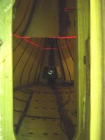
"Upside down" interior work: While the hull is still in an
upside down position it is a convenient time to make the fillets that supports
the horizontal parts like the cabin floor, settees and chart table.
Looking for
a material that is able to follow the hull shape and in the same time remains
horizontal I found Styrodur insulation foam to be the suitable material. All
positions are marked with a laser and the mold is formed by the Styrodur which
is
supported by temporary pieces of wood. Because of the light weight of the
Styrodur it is easy to fix with a 3M glue spray.
Turning
the hull upright: Turning the main hull upright is once again a milestone in
the project after which a new phase in the build starts. Farewell strong back,
the base construction on which all the hulls has been build, is now demounted in
little pieces and removed to the dumpster. With my four electrical winches under
the roof of the workshop, the actual turning went flawlessly. Of course I did it
alone again and to continue to fully concentrate without prying eyes of others.
With some extra ropes and the back-up of the workshop crane I took enough safety
precautions to avoid any risks.
For the support of the hull in the next phase of the build I've build two mobile
boat stands. For the subsequent assembly of the mainhull and the two floats the
boat have to be more or less moveable without too much of a hassle. I used the
hull as the mold for the two boat stands.
Preparations for the deck laminate: Now is the time to think very seriously
about the deck lay-out. During the whole build I have been pondering with a few
different options about rigging and hardware.
A deck stepped boom resolves the problem caused by lines (reefing lines,
outhaul, mainsheet) coming from the boom and interfere with mast rotation. I
made a mock-up to see how big of a problem this is and also studied a lot of
photo's of the big 60' Orma Tri's. My conclusion is that it is not worth the
extra trouble and the interference with mast rotation can be minimized by making
the line exit in the boom a little more aft of the mast. So the boom will be mounted to the
mast "the normal way" with the advantage that the boom induces the mast
rotation.
I can see the advantages of the self tacking jib. However, there are some
complications. The track crossing the daggerboardcase interferes with the
daggerboard and the length of the track is limited by the folding movement of
the beam. Nevertheless (I'm getting older and looking for more sailing comfort)
I have decided to go for the self tacking jib and I assume that I am able to resolve
this in the finishing phase of the build.
Furthermore I decided to make a curved track for the mainsail sheet traveler.
Probably the traveler will be extended to the beams, but this is also of later
concern. The mainsail sheet goes to the winch on the port side of the cabin
roof.
And finally I have designed a plan to organize all running rigging from mast to
the winches on the cabin roof. With the above starting points and the
running rigging plan I am now able to put in all high density foam inserts in
all these places where hardware will be bolted down.
Cabin
windows: The design calls for screwed down windows, but I don't like that
solution. Instead I want to glue them in a rabbet. The outside of the window is
then about flush with the outside of the hull. Determining the size of the
intended windows, also a little different from plans, was a challenge to get it
right. Finally I found out that I get the best appearance when the length
halfway the height of the window is about the same for all three windows. The
glazing material is smoke grey acrylic. The windows are curved in two directions
and I prefer to make them pre-curved instead of pressing them in the right
curve. So, first thing is to make a mold with the right curve in it. I did this
by infusing a sandwich panel against the outside of the cabin wall.
I outsourced the windows to a
local specialized company, de
bootruitenspecialist. They used my molds to make the acrylic in the
right shape. The result is fabulous and the windows fit perfectly.
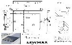
Deck
hatches: Well, it is a one-time opportunity so I choose for the difficult
option of flush hatches, which I found in Lewmar as the most economical ones. I
like fresh air and lightness and ordered one size 60 in the fore deck, two size
10 in the head and opposite passage way, two size 30 in the cabin roof and one
size 54 in the aft cabin. Flush with the deck means also a water drain below the
deck and that will be the next challenge to resolve.
In an earlier stage I made the escape hatch. In
this gallery you can see some photo's of the making of this part. When I made this
part the dimensions were based on a heavy duty Lewmar model.
Aft
cabin and cockpit construction: With respect to the vacuum infusion of the
deck there is a natural separation between the deck and roof of cabin and aft
cabin, as a result of the aft beam construction. So it is not necessary to
infuse the whole deck at once and therefore I have decided to first infuse the
roof of the aft cabin so I can finish the construction of the aft cabin and
cockpit.
To get some more room in the cockpit I made the seats 175cm long (my body
length) instead of the 168cm in the plans. (for nice romantic sleeping under the
stars, etc, etc.) After the mounting of the aft cabin hatch it turned out that
I've been a little too enthusiastic with the lengthening of the cockpit seats.
To make the hatch fit I had to make a cut out in the bridge and that just didn't
look very well. The other option, positioning the hatch more aft, is not
desirable because of the position of the main sheet track. Repositioning the
latter results in less pushing force in the boom to help mast rotation so the
mainsheet track dominates the position of the rear of the hatch. To resolve this
I've added two extra foam panels to the front panels of the aft cabin which
resulted in a correction of 32mm, which is just perfect.
Oh well, it seems you shrink as you get older.
Deck
laminate and vacuum infusion. Finally it is time to finish the final
structural part of the main hull. This is also the last big vacuum infusion.
After this the hull is structural sound and finished except for the final post
curing. It is a big bag of 12x6m and the infusion strategy is again a simple
straight forward setup with just 4 single vacuum ports and a resin feeder line
going all around. Vacuum integrity on the outside of the hull, as with the
vacuum bag for the bottom, is much more difficult to get it right than
with the vacuum bags on the inside of the hull. But with the help of my
wife and son we finally got it right.
On the left the video of the infusion and you can find the photo galleryhere.
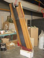
Rudder
construction part one, the rudder blade: During the construction of my boat, I have gotten a lot of relationships with other boat builders, both
domestically and abroad.
The exchange of experiences has proved extremely valuable and is also one of the many fun incidentals of such a DIY project. Here
in the Netherlands are two fellow boat builders who are both involved with CNC technology.
Bert (F39) as a professional and Nico F82SR)
as a hobbyist. The fabricated parts and the mold for the daggerboard are being made by Bert. And just recently Nico offered to
make the two rudder plug halves for my F39.
Nico is an airline pilot and spent his lonely days somewhere far away in a hotel room on the programming of hundreds of lines in
the CNC software for my F39 rudder. Great job Nico and thanks again. After
finishing the rudder blade mold, it is not much extra work to make a spare
rudder blade. So, I've made two rudder blades.
Steering studypage:
Designer Ian Farrier provides various options for the steering possibilities for
the F39. Unfortunately none of these meets my needs.
There are two kinds of sailors. Those who like tillers and those
who like wheels. First of all there is the choice for
tiller or wheel. Just like everything else to do with boats, the wheel/tiller
debate is highly subjective. Both systems have their own pro's and con's. I
always had boats with tiller steering. For me this alone is a good reason for a
change. One of the advantages of a tiller, the simplicity with only a few moving
parts, is not going to work in the F39 centre cockpit. Like the wheel steering a
tiller also needs some kind of
mechanical
transmission to the rudder stock.
Then there is the aspect of space. The tiller divides the
cockpit in a starboard and port part. In this rather small cockpit this
compromises access to the coveted space under the dodger. The wheel on the other
hand divides the cockpit in a fore and an aft part. The helmsman has is own part
of the cockpit. I love that more than a sweeping tiller. Standing behind a wheel
while maneuvering in close quarters is more comfortable than with the tiller
between the knees.
So, for me enough reasons to go on with a wheel.
Now what size?
a size small enough to walk along is not what I want. In that case I would have bought a sports boat ;) So as
big as possible which turned out to be 900 mm. at a height of 800 mm.
As now these basic questions have been answered the next step is the most
difficult one. The decision about the transmission system. Roughly there are
four basic types, in order of my preference :
1. Rack and Pinion steering - sound and
straight forward, good rudder feeling. 2. Transmission
steering - sound and good rudder feeling; 3. Cable or rope steering - in my opinion too prone for faults so
not for me; 4. Hydraulic steering
- no rudder feel, also not for me;
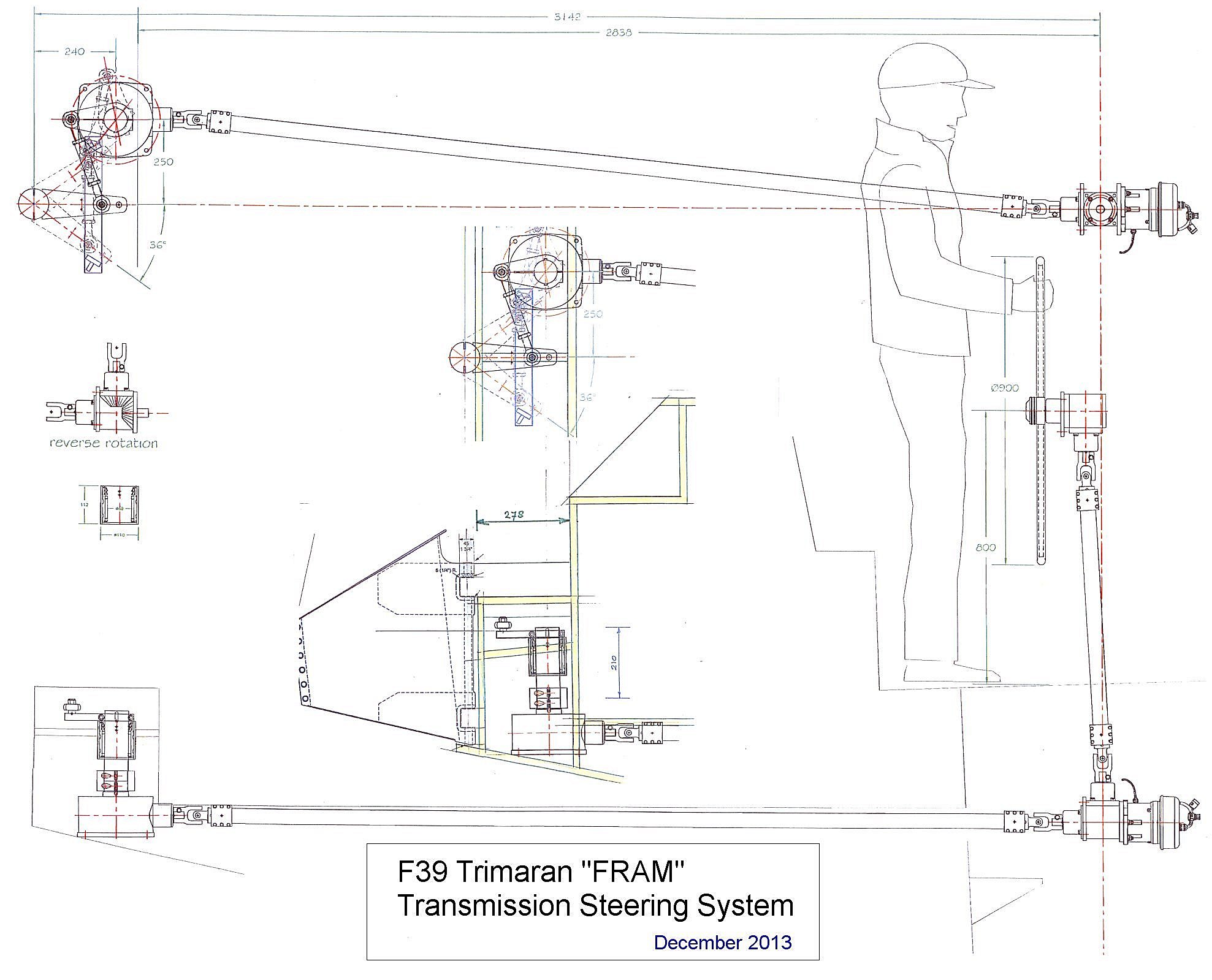
Transmission steering system: Although I prefer
the rack and
pinion option this system didn't made it till the
implementation stage. The space in the stern is too small and too narrow to make
an optimum use of a
wide angle geometry.
This smart geometry results in a
very direct steering amidships (where the loads are low) and a more indirect and
powerful steering at full rudder (where the loads are maximal). Also the
draglink from pedestal to rudder, with a length of almost 3m. (10ft) , needs a
lot of space for its movements and thus a big hole in the aft beam bulkhead.
Enough
reason to forget the rack and pinion system.
While maintaining the wide angle geometry I decided to change over to
a
transmission steering system made by the Danish Jefa. This system is based on the same principals as the rack and pinion system; the rotation of the wheel is transferred to a push pull movement via a gearbox and levers.
However, also due to the limited space behind the
transom, the proposed position of the bevel reduction gearbox is too far aft with
the consequence that the position of the torque tube doesn't match with the
height of the cabin bed. The torque tube is intended to go underneath the bed
bottom.
The solution is to position the whole rudder 96 mm further forwards. This
means that the wideness of the lower step in the stern has to change from 374 to
278 mm. Resulting in a 210 mm. extension of the reduction gearbox shaft.
The above drawing is the final design and Jefa parts. The bevel reduction gearbox
is housed in its own watertight compartment and separated from "outside" by a
watertight roller bearing. The connection of the autopilot drive is at the front
of the bevel box right under the steering pedestal. The autopilot drive will be
ordered at a later moment.
I have high expectations of this steering system. The only drawback I can
think of is the considerable weight of the bevel reduction gear box that far
behind in the boat.
Rudder
construction part two, the rudder sleeve and case: After the making of the mold for the rudder blade it is not a lot of extra work
to make two rudder blades, as I want an extra one in case of a fatal rudder
damage. In fact, I make two complete rudder systems, one spare system in case of
a fatal rudder damage..
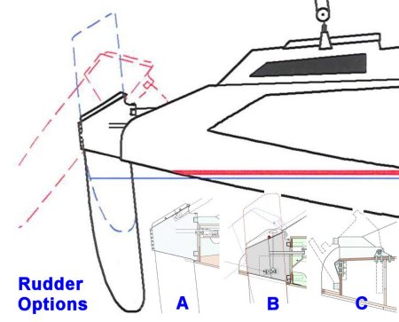
Designer Ian Farrier
provides various options for the rudder system. The main choice is between the
underslung rudder (not shown in the drawing) and the daggerboard style rudder. I
prefer the latter as this system gives a better steering control for getting in
and out shallow waters as it can be raised up and down.
The daggerboard style rudder system comes in three variations, in this
drawing called A, B and
C. The difference is in the manner in which the rudder blade
kicks back should any object be struck.
The
rudder option C with the hinged rudder box is only suitable for a steering system with cables and therefore
not suitable for me because it does not fit in my chosen transmission steering system.
After all, this system requires a fixed connection to the steering arm of which
position is not affected by a pivoting movement.
The rudder option B is my preferred rudder system and consists of a two-piece
pivoting case and sleeve.
Should any object be struck or the rudderblade hits the bottom, the aluminum rudder lock
bar will break, allowing the rudder to kick back preventing any more serious
damage.
Rudder option A is much simpler but will not kick back should any object
be struck. However, the case should split apart down the aft edge (with aluminum
bolts sheering) to allow rudder blade to kick back without any damage to the
transom. But some damage to the rudder case is likely to occur, which I
can confirm from my own experience which such a system on a F33. Due to the
simpler construction this will become my backup and emergency system.
Daggerboard construction:
For a long time I thought I was going to make the daggerboard
in the same way as the rudder. So, with the aid of a mold. To which I have just postponed
that for some reason. But at the finish of the main hull the appropriate
daggerbord case slot must have been created. A good reason at last to make that
daggerboard. I made it almost according to the plans, so with a Western Red
Cedar wooden core. But to prevent this core in case of a collision with
something, or hitting the ground, I made two changes to the plans. First a
leading edge with a high density glass fiber behind, instead of the wood, and
second a bottom part with a foam core. In addition to these changes and for
structural reason I replaced the wooden core in the leading edge by a glass
fiber core. Photo's are better than explaining by words. You can find them
here or by clicking in the daggerboard image at right.
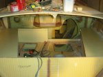
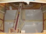
Aft cabin interior: Access to the aft cabin is easy through the still
open transom. In building the interior of the aft cabin I have take advantage of
this stage as much as possible. The work was quite complicated because of the
routing of the transmission steering components and my wish to have a waterballast tank at the front of the transom. On both sides of the cabin I have
made cupboards.
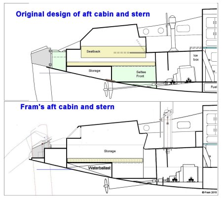
Finishing the stern:
I have been a long time puzzling how to end the stern. In the original design it
is a too big step from the stern platform to the aft cabin roof. In fact, a step
is missing in between. On my wish list was also a virtually rainproof portlight
in the stern, off course rainproof when it is open. In order to achieve this,
the portlight must be mounted under a kind of awning. Now I have realized this
by integrating an extension of the cabin roof with an extra step in the transom.
And a bonus not to be underestimated is that the aft cabin has become much more
spacious by this change.
Another wish that I had was that the rudder is more or less being protected by
the hull. With the realization of a larger scoop it was also possible to include
an additional step in the stern. The necessary extensions of the hull and the
roof of the aft cabin were realized in a much earlier stage. I had all these
changes already in my mind during the construction of the hull.
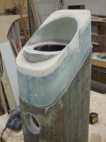
Steering
pedestal: The bevel box that connects the vertical torque tube in the
steering pedestal and the horizontal torque tube to the reduction gear box is
also the base for the autopilot drive. The bevel box needs a sturdy base but
still floats somewhere above the engine. There are various solutions thinkable
but I choose to lengthening the steering pedestal tube. This is the main reason
why I decided to make the steering pedestal myself. At first I had wild plans to
design my own but at the end I just copied the type 150 of Jefa. However, I have
underestimated the amount of work and it took a lot of time. Another complication
is that the Jefa tube is an aluminium tube with a wall thickness of about 3mm.
or so while my composite construction has a wall thickness of about 20mm. While
maintaining the same outside dimensions I made it for myself quite difficult.
The dimensions of the bevel boxes with their flanges require extra recesses in
the foam. But all in all the result is satisfying
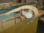
Bow wing and anchor gear.
The plans call for an 75 to 80mm fiberglass or carbon tube. Instead of buying
such a tube, I made the tubes myself the easy way, with a foam core (rounded 5
layers of 15mm Corecell)
Already at an earlier stage, I decided to refrain of the designed anchor
locker in the bow. The bow is the worst place to stow a lot of weight, and no
locker gives much more interior space. Besides of that, I'm tired of bringing
the anchor home by elbow steam so I decided to mount an electric windlass and
the combination with the designed anchor locker is not a logical one. It is best
to bring the weight of the windlass, chain and rope as far aft as possible. Just
in front of the forward sub beam bulkhead is ample space to create a large chain
locker and the same space gives also the opportunity to bring the windlass below
deck. The consequence is a chain pipe through the deck between bow wing and
windlass locker.
An investigation into windlasses taught me that the vertical type is the most
suitable for my application . This is because of the space available in the
windlass locker and the improved 180 degrees grip on the gypsy with respect to a
90 degree grip on the gypsy of a horizontal winch. An unforeseen problem
occurred when I discovered that most vertical windlasses turn clockwise when
hauling the anchor. Because the winch will be mounted on the starboard side
means that the chaintube comes too far to the outside of the bow wing and the
chain must go downwards along the wall of the chain locker. That's not a good
setup and I would rather saw a winch that turns counterclockwise at hauling of
the anchor. Now all winches can turn both sides, but it is the chainpipe that is
fixed on the port side of all vertical windlasses . Only the brand Quick offers
a left and right version, but unfortunately only for the larger types (Regal,
Dave, Duke). However, the smaller Rider model comes without a chain pipe and an
email to the Italian manufacturer confirmed me that I can make a DIY solution
for the chainpipe on the starboard side of the windlass.
So I purchased the Quick Rider 1000W 24V with 8mm/14mm chain/rope gypsy.
Next question is which anchor to use. I'm familiar with CQR, Bruce, Danforth,
FOB and Fortress anchors but the new generation anchors appears to be superior
to these traditional models. The various tests prove that Spade and Rocna are
the best performers and with regards to their seizing guides I need an anchor
with a fluke surface of about 1400 cm², which is a Spade S140 or Rocna 25. A
nice feature of Spade is that their 140 model is also available in an aluminum
lightweight version.
With their 1:1 patterns I made a wooden mock-up of both versions to determine
the possibilities for stowing the anchor on the bow wing. The length of both
anchors are about the same but the height of the Rocna 25 is much less than the
height of the Spade 140. Last but not least, the Rocna is considerable cheaper
than the Spade and the lightweight Spade is far beyond my budget.
So I purchased the Rocna 25.
Water
ballast: The aft part of the F39 must be kept as light as possible. However,
when running downwind in big seas and strong winds some more weight in the stern
is desirable. Actually I don't know if I need extra ballast in the stern but in
this stage of the build and with just a little extra effort I have the
opportunity to make a sea water ballast tank in a further not usable part right
in front of the transom. I guess that the maximum content of the tank will be
about 500 liter.
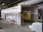
Postcuring:
I have been waiting for the summer for a sufficient room temperature to undertake
this process. The infusion resin used by me must be post-cured at a temperature of about 80
degrees Celsius for 8 hours.
That is quite a lot
to achieve by simple means. Together
with my son we have built an "oven"
consisting of 100 mm.
polystyrene sheets encased
in prefabricated particle board H-beams. Making these H-beams
was a -quick and dirty- job which resulted in the collapse of the roof. The
fixing method with (too small) staples did not appear to be resistant to the
high temperature. 60mm. screws did a better job. This was actually the only
setback and the rest of the process went very well. Two diesel heaters at both
ends of the box together with a workshop room temperature of 25 degrees were
sufficient for the desired 80 degrees Celcius oven temperature.
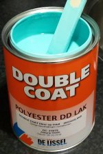
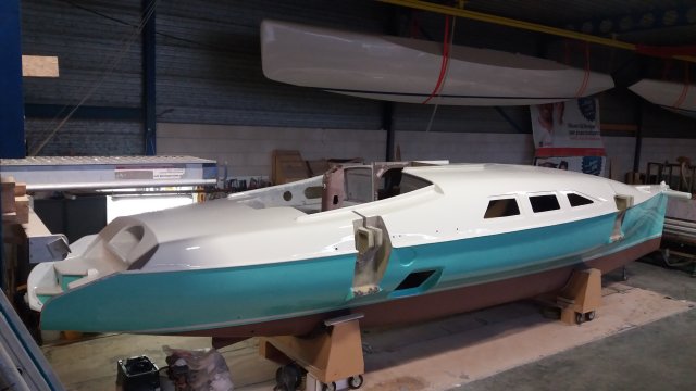
Fairing
and painting:
I am very happy with the final appearance of the floats. The paint job is great
thanks to the thoroughly preparation and lots of effort in the putty and sanding
process. However, the fairing of the hulls with the fairing board was a time
consuming and very tough job, to be honest a hell of a job. With the purchase of two wide flexible filling knives
at Flexisander, one 2' wide (600mm) and the other 4' wide (1200mm), I now choose
for a different approach for filling, fairing and sanding process of the main hull.
My goal
is to minimize the hard work with the long fairing board and maximize the use of my sanding machines.
The trick is to shape the fairing compound with the long filling knife in one
continuous stroke, preventing excess fairing material and when done to not touch
it anymore. The next part to shape is the width of the putty knife apart. After
(partly) curing it is the turn for the parts in between. When finished this is
the first layer
of faring compound. The second layer, which uses much less
fairing compound, is thereafter applied in such a way that this is overlapping
the first areas. The whole job has been done with the 4" wide knife which gives
a very fair result and minimize excess faring compound. The
use of the random orbital sander with grid 40 sanding paper is now mainly
in order to make the surface more smooth. This requires some skill
to avoid sanding to deep.
The last step is the overall fairing with the long flexible faring board. As the
hull is already very fair this is not much work anymore. My last step of the
fairing process is applying one final layer of a fine finishing fairing compound
which smooth out the grid 40 sanding strokes as well as the last imperfections.
The last part of this finishing process is sanding down the last fine layer of
fairing compound with grid 120 and apply the high build primer before finishing
with the two part high gloss paint.
About the color ..... Mint Green ..... It is a bold color
and provoked divided reactions. However, somewhere in the nineties I came across
a boat (the 40ft. monohull "
Epoxydus" that very much impressed me. It was mint
green with a white deck. I loved it.
Since that time I have
that color in my mind and now I have the opportunity
to make that true for my own boat. Only
the crew needs some more time to appreciate it ...... ;-)
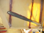
Three
hulls coming together: the final assembly of my trimaran. The transformation
of three hulls and four beams into a boat is the climax of the construction.
Finally everything comes together and leads to the trimaran I dreamed of. It is
definitely a highlight of the construction so far. But first to do is bringing
the floats down to earth. It's been a long time since we hung the first float
under the roof, followed by the second one. All those years they have collected
only dust but now they can come down again.
The port float is hanging above and behind the boat. To bring down the port
float I first had to make room next to the boat. The boat has to slide sideways
to create ample maneuver space for the forklift. With the help of two pallet
jacks the boat easily slides sideways. With a makeshift boat-stand clamped to
the forklift I carefully lifted the float, unscrewed the tensioning straps the
floats were hanging in and bring it down. However, maneuvering with forklift and
boat only takes one way. The port float is still looking in the wrong direction
but turning is not possible because of lacking space. The workshop crane brings
the solution. In the free space somewhere in the middle of the workshop height,
I can turn the boat in the right direction and bring it back to the position at
the port side of the center hull. Fortunately the other float is much easier to
reach and is already hanging in the right direction. There is still not enough
maneuvering space for the forklift but taking it over by the workshop crane
brings the float to its position at the starboard side of the center hull.