I made a lot of photo's of the building process. They are compiled in
photo albums and you can find them by clicking on the pictures in this
page.
Setup port float: I purchased the F-36
plans first and was lucky to get the used form frames from
Gary Mulder's F-36
With some modifications they are useable for the F-39 floats too, but I
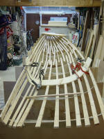
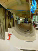
preferred to make new ones. First step is the setup of the temporary
frames for the outer side of the port float.
I hope to learn the tricks in this one as this side is a little easier
to make than the inner side.
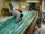
 Thermoforming
the vertical foam strips: This is my first time building a boat with
CoreCell foam and the answer to the question "How to bend the foam?" turned out
to be pure and simple. But before that was recognized, I tried to make it
much more complicated than necessary. So, the first attempt was with a "hot
box", main reason because other builders are doing this also (?!). Thermoforming
the vertical foam strips: This is my first time building a boat with
CoreCell foam and the answer to the question "How to bend the foam?" turned out
to be pure and simple. But before that was recognized, I tried to make it
much more complicated than necessary. So, the first attempt was with a "hot
box", main reason because other builders are doing this also (?!).
Fortunately too much of a pain for me and the hot box creation I made
turned out to be unsuitable and disappeared in the rubbish dump. But why
always doing the things the hard way first? It was easy to bend the foam
in place by just heating the foam with a heat gun while pushing it into
the form.
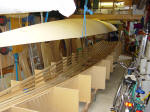
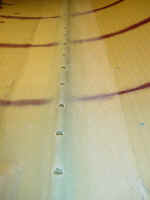
For the vacuum infusion I need a airtight foam hull, so screwing down
from inside through the foam is not recommendable. The strips are mounted
"dry" and the joints between the strips are milled with a Dremel tool and
filled with microballoons afterwards. This gives me the best assurance
that the joints are sufficient impenetrable. The foam strips are 400
mm. wide in the middle of the hull to 300 to both ends.
 With these economical sizes I can get 3 or 4 strips out of one plain sheet
(1220x2440 mm.)
With these economical sizes I can get 3 or 4 strips out of one plain sheet
(1220x2440 mm.)
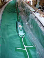
 Controlled vacuum infusion: Now the
biggest moment and the answer to the question "Will my approach to this
boat building project be successful ??" The answer is a heartily YES! This
is the best that happened to me lately. A building method with resin
infusion with guaranteed results in the best quality one can think of and
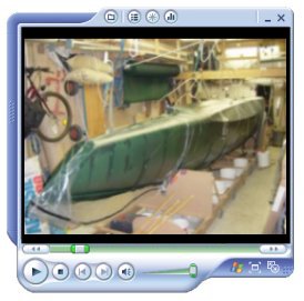
all that within my range of skills. Click on the vacuum
infusion animation to enlarge and click in the picture left to see the laminate lay-up and the resin infusion of
the first float half. Amazing isn't it! No doubt a highlight and reason
for a party. Controlled vacuum infusion: Now the
biggest moment and the answer to the question "Will my approach to this
boat building project be successful ??" The answer is a heartily YES! This
is the best that happened to me lately. A building method with resin
infusion with guaranteed results in the best quality one can think of and
all that within my range of skills. Click on the vacuum
infusion animation to enlarge and click in the picture left to see the laminate lay-up and the resin infusion of
the first float half. Amazing isn't it! No doubt a highlight and reason
for a party.
(note: many years after writing the above, I learned that this one shot infusion
of a hull together with elements such as stringers is called "3D infusion"
(source European Boatbuilder Magazine no. 43 May 2010)
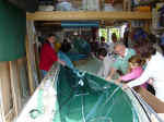 Festively
revelation: A good tradition when laying down the keel in a boat
building project is the celebration of this milestone. Only problem with a
trimaran is the absence of a keel (?!) Festively
revelation: A good tradition when laying down the keel in a boat
building project is the celebration of this milestone. Only problem with a
trimaran is the absence of a keel (?!)
But this first infused hull half was a nice alternative to celebrate the
successful start of the boat building enterprise with a festively
revelation by family and friends. (though I had to disappoint some friends
who thought I will do this with every hull .......... )
 Bulkheads:
I made the first (and last) bulkheads with hand lay up and vacuum bagging
before I discovered that vacuum infusion was a much easier method to do.
Among With other infusing details the infusion of the combined
bulkheads (in one panel) for the next float is covered in a step-by-step
video that's part of the available
resin infusion kit. Bulkheads:
I made the first (and last) bulkheads with hand lay up and vacuum bagging
before I discovered that vacuum infusion was a much easier method to do.
Among With other infusing details the infusion of the combined
bulkheads (in one panel) for the next float is covered in a step-by-step
video that's part of the available
resin infusion kit.
In this album also some photo's of the making of the foam stringers and
cutting off the stern.
 Carbon
fiber chainplate: Making of the carbon fiber chainplate. A stainless steel
thimble on top of a foam strip, wrapped with UD carbon fiber. The chainplate is
prepared for synthetic rigging with Precourt deadeyes. To maintain control over
the straightness of the lay up of the carbon fibers, this part is not vacuum
threatened. Carbon
fiber chainplate: Making of the carbon fiber chainplate. A stainless steel
thimble on top of a foam strip, wrapped with UD carbon fiber. The chainplate is
prepared for synthetic rigging with Precourt deadeyes. To maintain control over
the straightness of the lay up of the carbon fibers, this part is not vacuum
threatened.
With all these lessons learned it's becoming high time to start with the
second hull half. Because of the limited room in my workshop, I have to
make the second hull half of the same float now. This creates an extra
setup of the form frames with the fore and aft battens. But I can do this
quicker than moving the hull half for storing in another place. The new
setup took less than 8 hours.
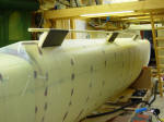
 Planking
the second hull half: The hull halves are not symmetric, due to the raised
deck area. The form of this half is not "self-releasing", in other words, the
raised deck area "hangs over". This required an other setup of the battens in
that area, which will allow to remove these battens while the hull is still in
the form frames. By the way, Ian Farrier recommends to leave this area
unlaminated and to bent into shape after removing the hull from the form frames.
This is probably easier with hand-lay-up lamination, but not suitable with my
resin infusion technique. Planking
the second hull half: The hull halves are not symmetric, due to the raised
deck area. The form of this half is not "self-releasing", in other words, the
raised deck area "hangs over". This required an other setup of the battens in
that area, which will allow to remove these battens while the hull is still in
the form frames. By the way, Ian Farrier recommends to leave this area
unlaminated and to bent into shape after removing the hull from the form frames.
This is probably easier with hand-lay-up lamination, but not suitable with my
resin infusion technique.
 Next
resin infusion party: Most important thing I've learned is that any
leakage is a no-no. Where I first thought an ultra sound leak detector is
just a waste of money, I had to reconsider this opinion. So, I purchased
one from Airtech to be able to find that very tiny bastard, virtually
unnoticeable in this stage, but spoiling the fun during the infusion. On
the other hand, some extra attention with the sealant tape will pay back.
There is no rush to do this fast while there is no curing laminate as with
the hand-lay-up vacuum bagging. Next
resin infusion party: Most important thing I've learned is that any
leakage is a no-no. Where I first thought an ultra sound leak detector is
just a waste of money, I had to reconsider this opinion. So, I purchased
one from Airtech to be able to find that very tiny bastard, virtually
unnoticeable in this stage, but spoiling the fun during the infusion. On
the other hand, some extra attention with the sealant tape will pay back.
There is no rush to do this fast while there is no curing laminate as with
the hand-lay-up vacuum bagging.
Pleats in the bag are unavoidable and even necessary to keep the bag from
bridging. A spacious bag is no problem, but too tight is. So, these pleats
are double sealed with the tacky tape. Making them is not difficult but
requires some patient and handiness. Ones understood every sealed bridge
will be tight, but if there are leaks in the bag this is the first place
to start looking. It is obvious that for a bag like this only dedicated
vacuum materials are suitable, a strong vacuum film and a special sealant
tape. Materials like the pvc or pe sheets one can buy at the local
home-store and window seals or duck tape are a waste of money and energy.
I tried the first bag with pvc, and it just did not work.
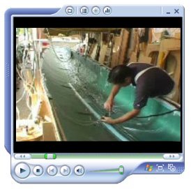
I made a video clip of the infusion of the second hull half.
Click the video image at the left to download this 3,3Mb film. On special request from
one of the e-group members on the Multihull Boatbuilders List I've added a John
Williams sound track to catch the accompanying ambiance ;-)
By the way, the video's in this page are the same as the one you
can find in the Controlled Vacuum Infusion page.
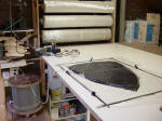
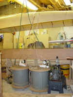 Vacuum
pump and resin trap setup:
I use two small (but able to achieve a deep vacuum) oil filled rotation
pumps, a fast running pump (in a former life used for maintenance purposes for
medical MRI equipment) and a slow running (and almost antique) pump (after a
long life in a scientific environment this pump is now used for his second
multihull building) This one runs continues without any problem (the fast
running pump is also able to run for a longer time, but is getting very hot,
which I don't like while unattended) The only worry is to close the vacuum tube
to the pump before switching of the power or to totally release the vacuum
first. Otherwise the oil will flow in the resin trap, not really a problem, but
a pity for the waste of oil. Tightness is crucial. I cannot afford any leakage,
because this will ruin the laminate, making an air bubble track from leakage
point to venting point. This is the advantage of a small pump. When there is
some leakage the pump is not able to achieve a good vacuum. Here is a warning
for big pumps justified, where a big pump is able to achieve a good vacuum while
you don't know there is a leakage some where. Vacuum
pump and resin trap setup:
I use two small (but able to achieve a deep vacuum) oil filled rotation
pumps, a fast running pump (in a former life used for maintenance purposes for
medical MRI equipment) and a slow running (and almost antique) pump (after a
long life in a scientific environment this pump is now used for his second
multihull building) This one runs continues without any problem (the fast
running pump is also able to run for a longer time, but is getting very hot,
which I don't like while unattended) The only worry is to close the vacuum tube
to the pump before switching of the power or to totally release the vacuum
first. Otherwise the oil will flow in the resin trap, not really a problem, but
a pity for the waste of oil. Tightness is crucial. I cannot afford any leakage,
because this will ruin the laminate, making an air bubble track from leakage
point to venting point. This is the advantage of a small pump. When there is
some leakage the pump is not able to achieve a good vacuum. Here is a warning
for big pumps justified, where a big pump is able to achieve a good vacuum while
you don't know there is a leakage some where.
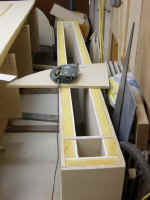
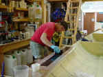
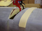
 Making
a tube (attempt): The wing nets are being attached to the hulls with a
moulded lashing rail, made out of a tube. To get some experience with this
system, I decided to make 3/4" tubes for attaching a net inside the float, as a
floor to store sails and other stuff in a dry and ventilated matter, and not in
the keel section of the float. Second advantage is that things are reachable
from the deck hatch, without the need for going in. Making
a tube (attempt): The wing nets are being attached to the hulls with a
moulded lashing rail, made out of a tube. To get some experience with this
system, I decided to make 3/4" tubes for attaching a net inside the float, as a
floor to store sails and other stuff in a dry and ventilated matter, and not in
the keel section of the float. Second advantage is that things are reachable
from the deck hatch, without the need for going in.Although good enough for
inside the float, I decided to buy ready made glassfibre tubes for the moulded
lashing rail for the wing nets.
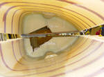
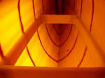
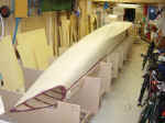 Combined
hull halfs: The float half still in the frames takes care for the correct
shape, while the hull half on top is out of shape between the bulkheads. Once
correctly aligned at both ends and bulkhead stations, this is not a real
problem. With some temporally screws the shape of the hull half on top is easy
corrected to the shape of the hull half below. With some bog between and taped
bulkheads in the middle, the now joined hull is strong enough to release from
the frames and, while turned in a convenient position, to go inside for taping
the keel and deck join. I am happy with my four electrical winches in the
ceiling, with which I can lift and turn the hull on my own. Combined
hull halfs: The float half still in the frames takes care for the correct
shape, while the hull half on top is out of shape between the bulkheads. Once
correctly aligned at both ends and bulkhead stations, this is not a real
problem. With some temporally screws the shape of the hull half on top is easy
corrected to the shape of the hull half below. With some bog between and taped
bulkheads in the middle, the now joined hull is strong enough to release from
the frames and, while turned in a convenient position, to go inside for taping
the keel and deck join. I am happy with my four electrical winches in the
ceiling, with which I can lift and turn the hull on my own.
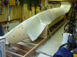 Outside
laminate in one infusion shot:
Now to the final climax for this hull, the vacuum infusion of the outside
laminate. The goal is to do the injection in one shot. Click on the
animation to enlarge the animation of the simulation of the outside laminate. Outside
laminate in one infusion shot:
Now to the final climax for this hull, the vacuum infusion of the outside
laminate. The goal is to do the injection in one shot. Click on the
animation to enlarge the animation of the simulation of the outside laminate.
I received a lot of
questions about the area were the hull rest against the cradles. The thought is
that the weight of the hull will disturb the epoxy flow by producing a
compression force in the laminate. Well, this is only a (small) problem in
the dry condition to keep the fabrics in their positions. During the infusion
the vacuum pressure is 1 kg/sqcm (this is 10 ton/sqm) and this force will
overrule the weight completely. The epoxy flow is in not any way influenced by
these supports.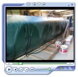
Click the video image at right to see a 8,7Mb video of the float infusion. On
the CVI page you can find a smaller 5,2Mb version.
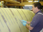
 Finishing
the construction: Wingnet fastening is with an integrated molded lashing
rail with a fiberglass tube. Another purpose of this rail is to create three
strong deck eyes, as an alternative for bolted SS pad eyes. The extra strength
is created by carbon reinforced foam pads, which goes through the hull and are
laminated to the inside, the middle one also in the shroud bulkhead. Also the
making of two deck hatches (with invisible hinges) and after all the glassing is
done, the final post curing of the whole hull before the fairing is going on.
The fairing and sanding turned out to be a real investment in learning time and
finally succeeded by dogged perseverance. It's the last 300 gram of fairing
compound that required the maximum effort. Finishing
the construction: Wingnet fastening is with an integrated molded lashing
rail with a fiberglass tube. Another purpose of this rail is to create three
strong deck eyes, as an alternative for bolted SS pad eyes. The extra strength
is created by carbon reinforced foam pads, which goes through the hull and are
laminated to the inside, the middle one also in the shroud bulkhead. Also the
making of two deck hatches (with invisible hinges) and after all the glassing is
done, the final post curing of the whole hull before the fairing is going on.
The fairing and sanding turned out to be a real investment in learning time and
finally succeeded by dogged perseverance. It's the last 300 gram of fairing
compound that required the maximum effort.
 Design change: After the summer holiday break
I received an e-mail from Ian Farrier, announcing that the preliminarily
drawings are now replaced by the final design plans, with some minor changes
...... One of them effected my job so far dramatic: the new designed beams are
much wider and won't fit anymore between my raised deck area. So I had to take
the saw for cutting some big holes, really not a nice job. The final fairing was
just finished, but on the positive side, due to my sailing holiday I didn't cut
in yet the lashing holes in the molded tube for the wing netting. Design change: After the summer holiday break
I received an e-mail from Ian Farrier, announcing that the preliminarily
drawings are now replaced by the final design plans, with some minor changes
...... One of them effected my job so far dramatic: the new designed beams are
much wider and won't fit anymore between my raised deck area. So I had to take
the saw for cutting some big holes, really not a nice job. The final fairing was
just finished, but on the positive side, due to my sailing holiday I didn't cut
in yet the lashing holes in the molded tube for the wing netting.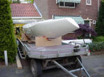
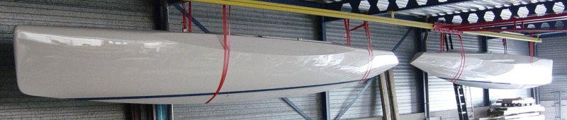
Final
painting and relocation: Finally the time is ready to move the hull to
another storage. After the final painting the hull is stored in another place,
waiting for the assembly with her starboard twin sister. >>
|