The engine installation focuses on a stiff composite foundation, precise alignment with the stern tube and Aquadrive system, and a quiet, efficient wet exhaust arrangement.
Engine Installation
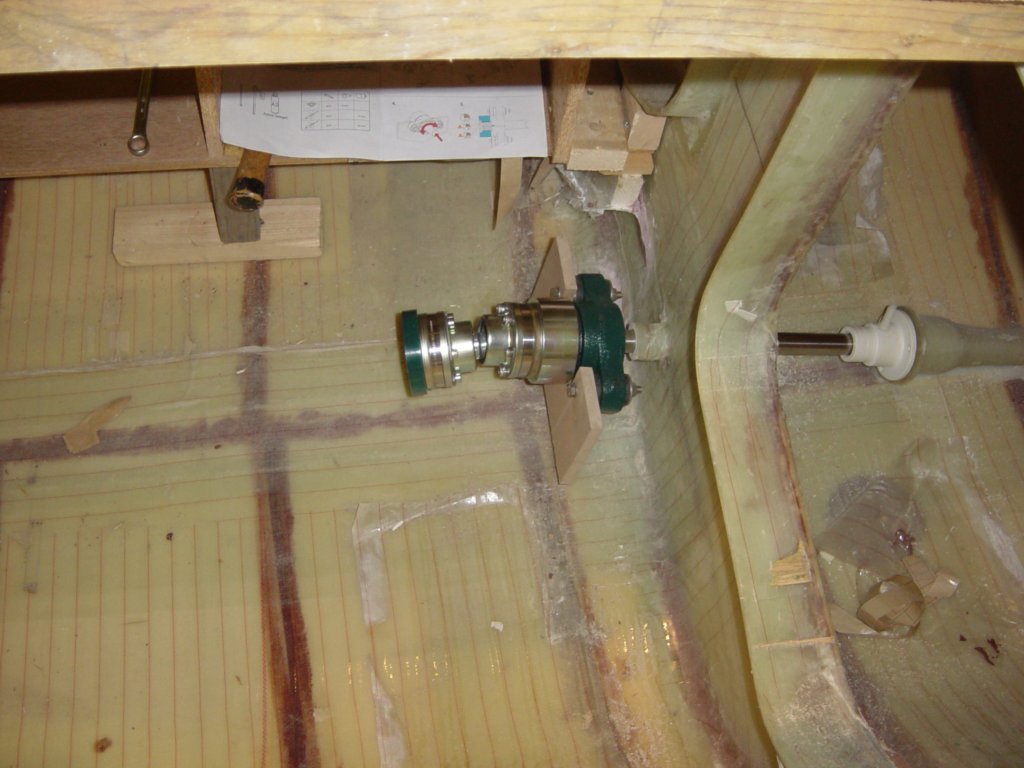
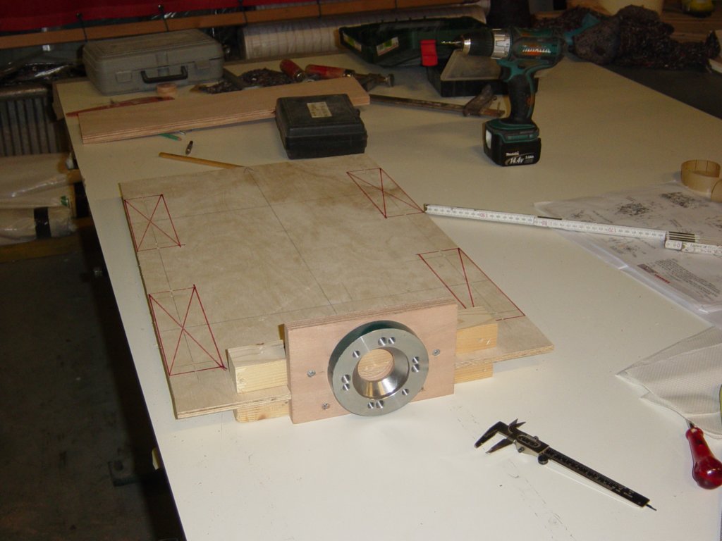
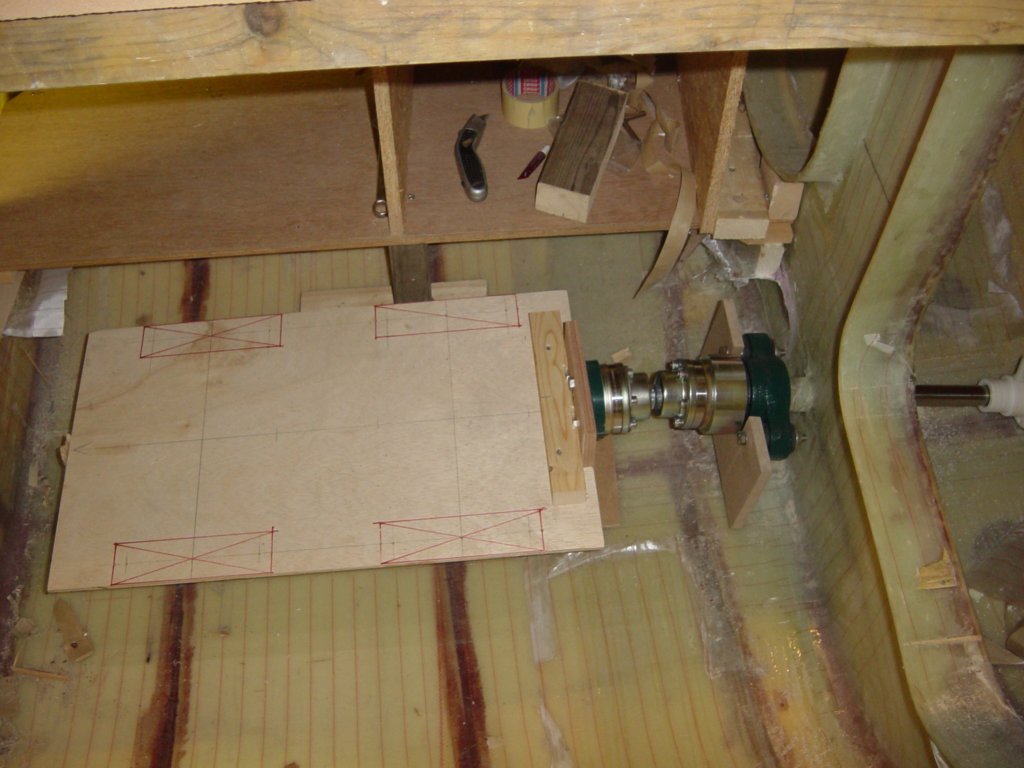
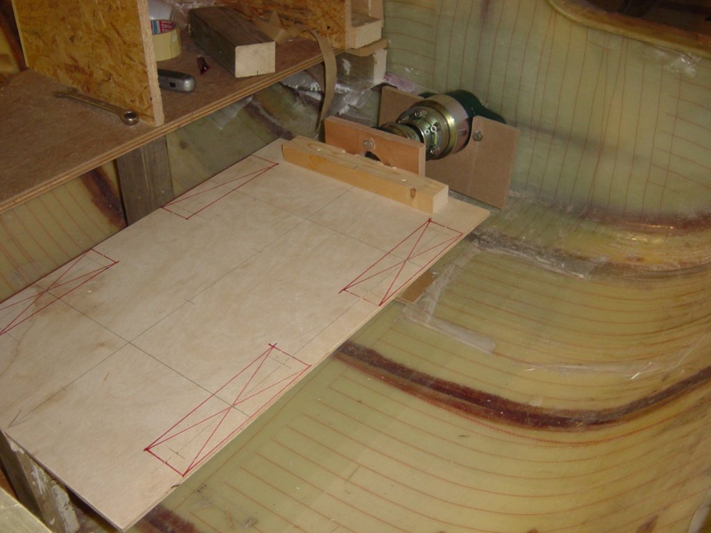
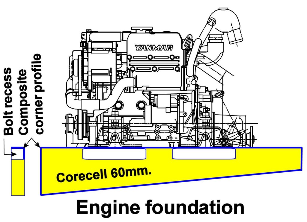
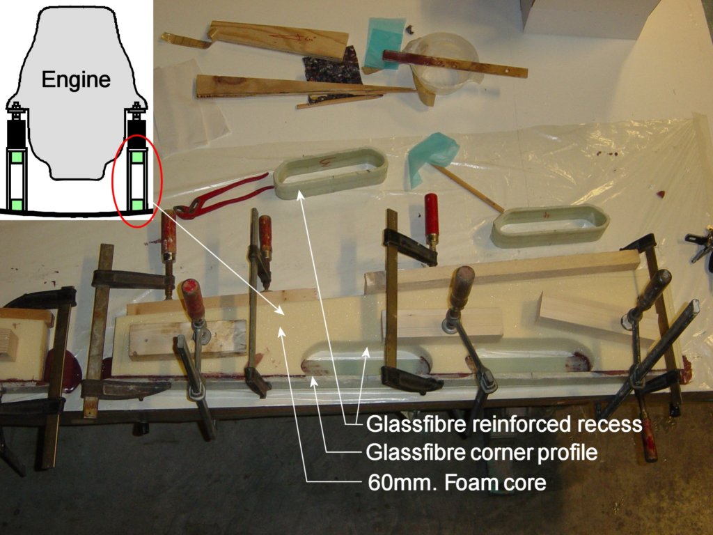
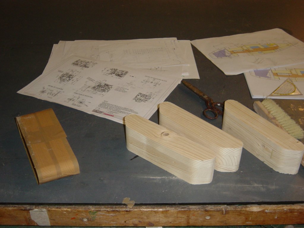
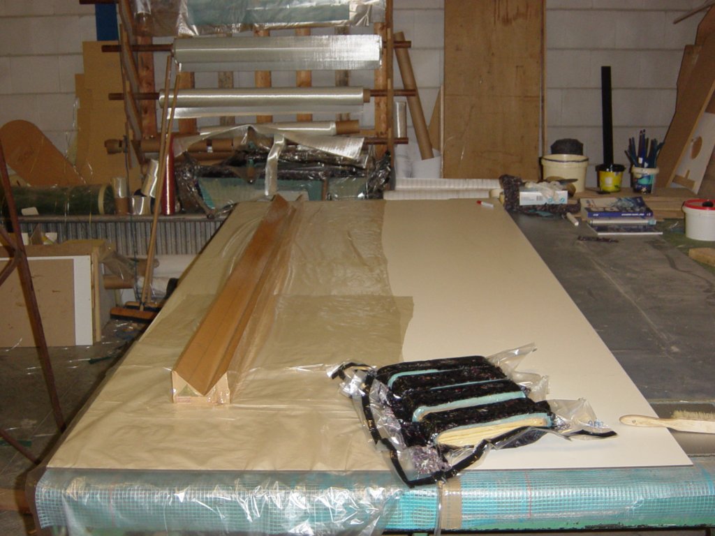
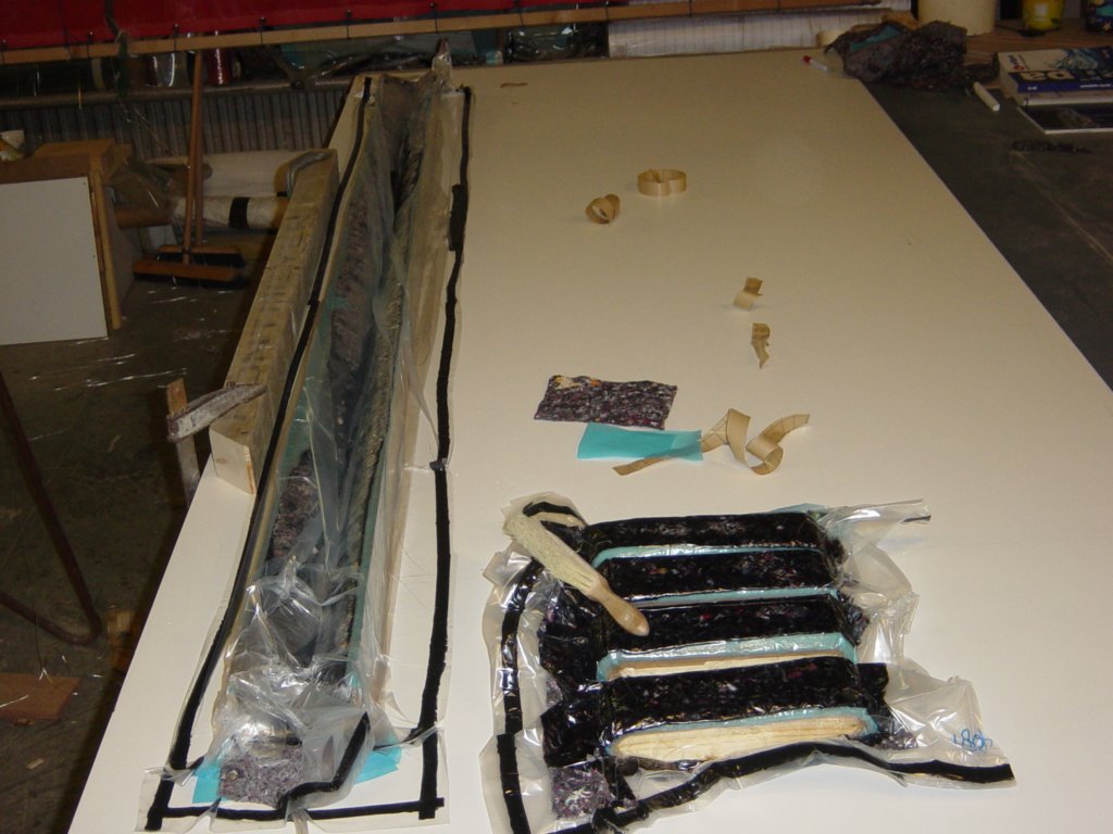
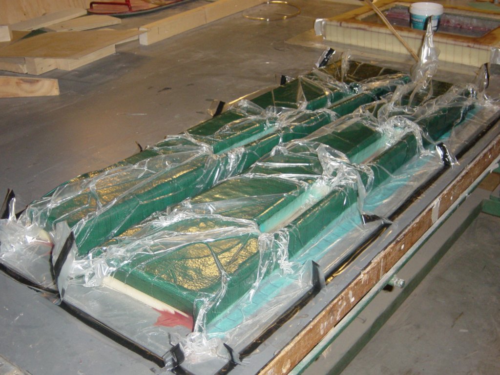
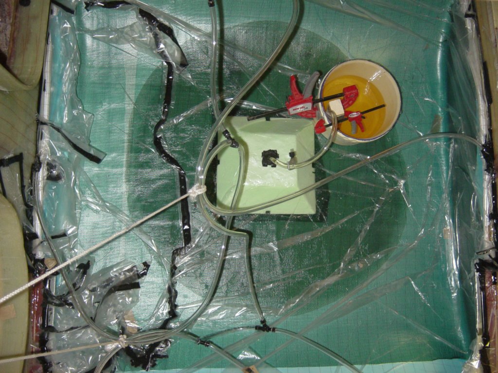
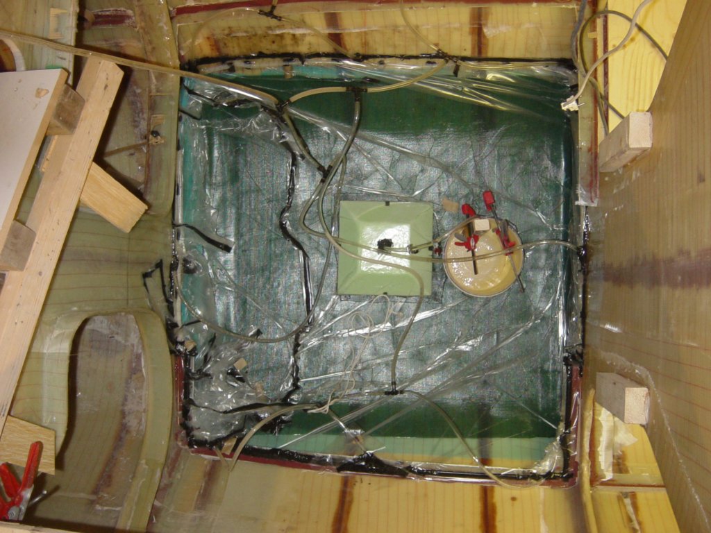
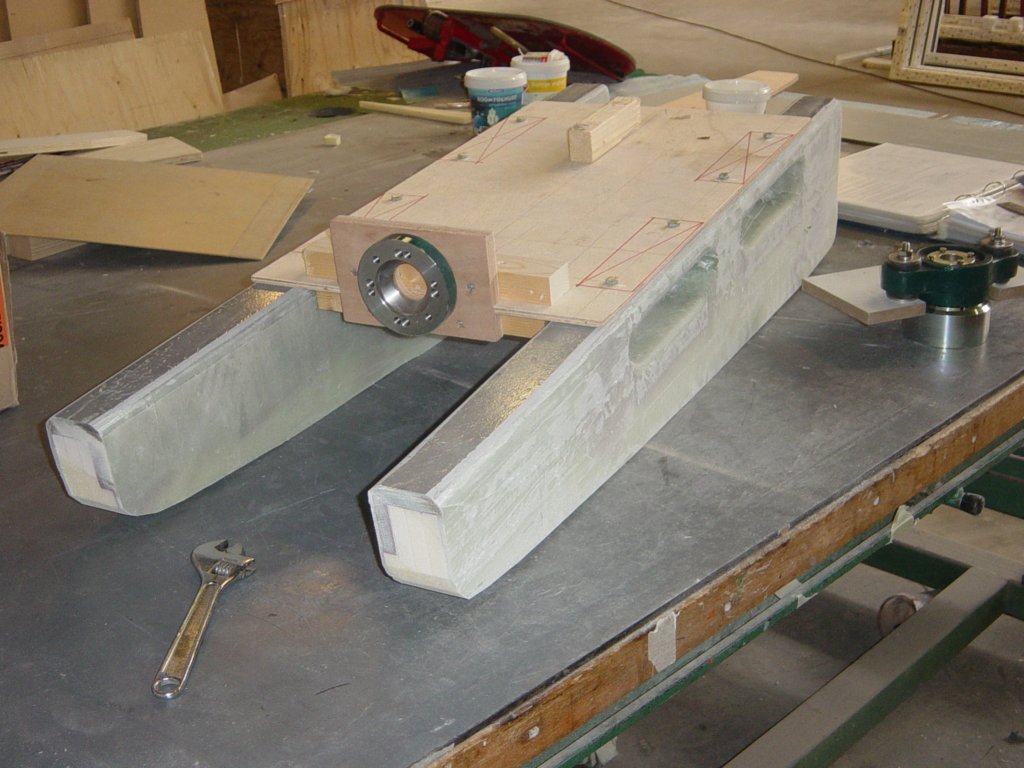
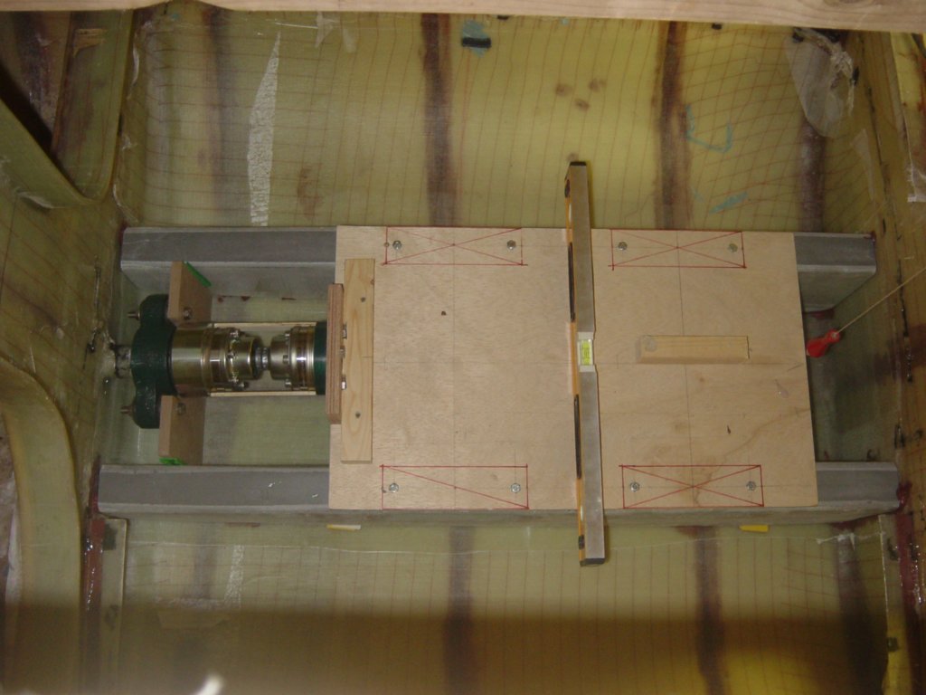
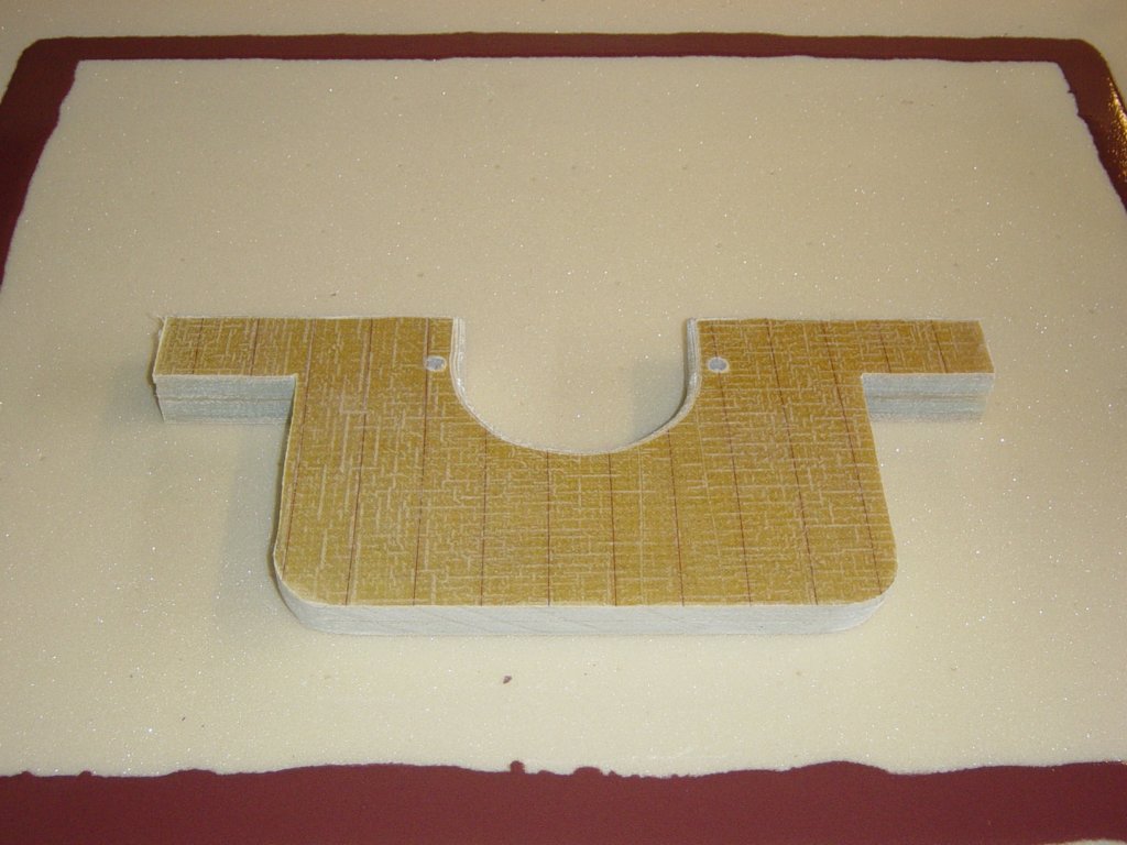
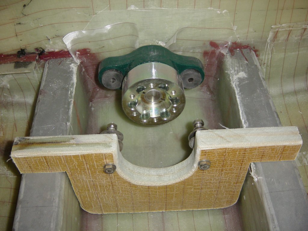
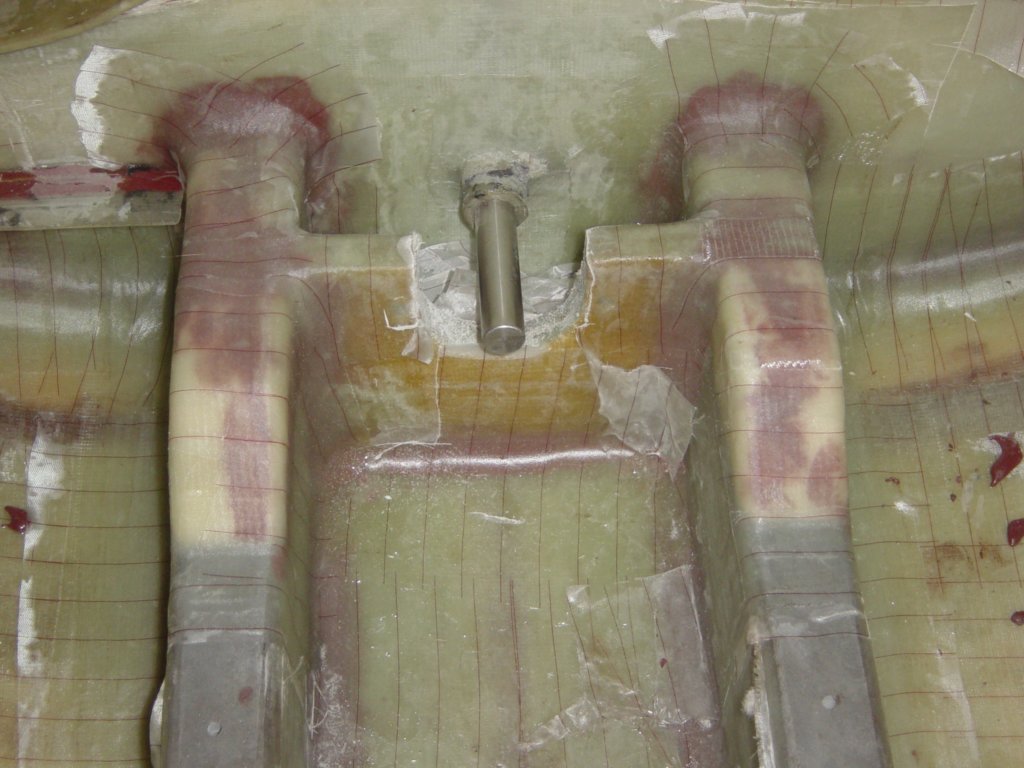
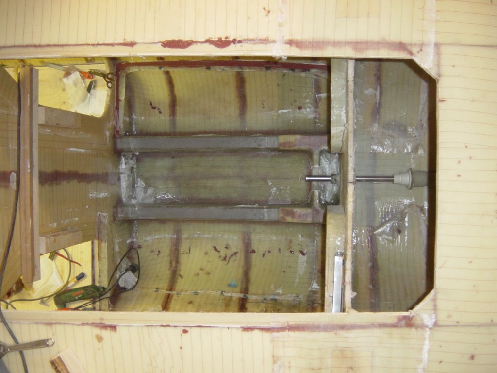
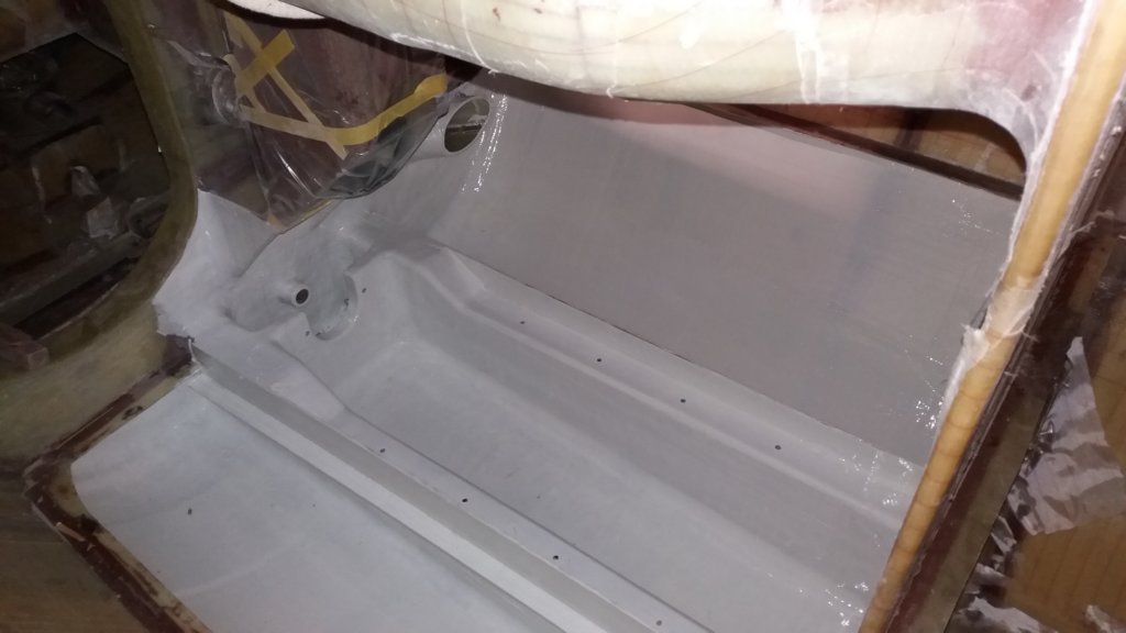
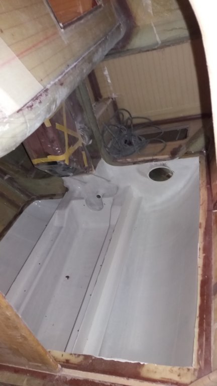
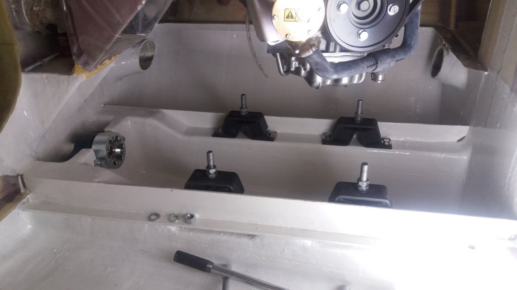
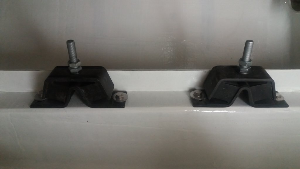
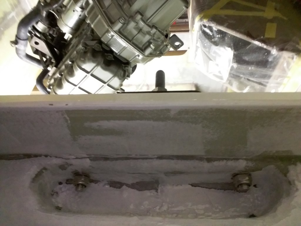
During construction of the cockpit, I also built the engine foundation. At that stage it was the most practical moment to do so. The plans specify longitudinal engine girders made from a 12 mm plywood web box with 40×40 mm wooden flanges all around. As I try to avoid the use of wood wherever possible, I chose a different solution. The girders were built from 60 mm Corecell foam (4 × 15 mm layers bonded together), with a glass fibre corner profile at the top and an additional six layers of 600 g/m² stitched glass fibre all around. For the engine mount bolts, reinforced recesses were integrated into the structure. To ensure correct alignment of the engine foundation relative to the previously installed stern tube, I used a wooden mock-up of the diesel engine.
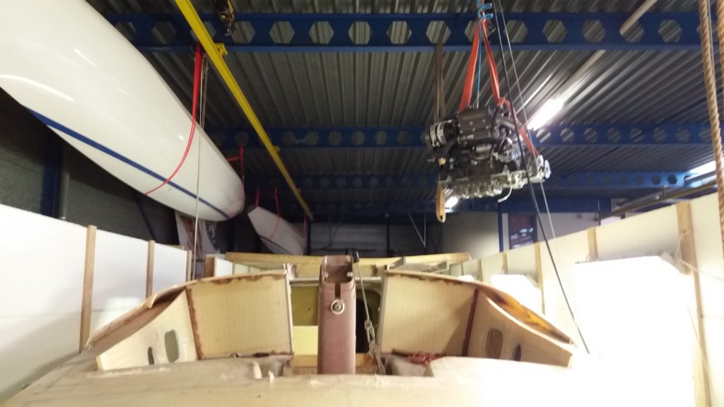
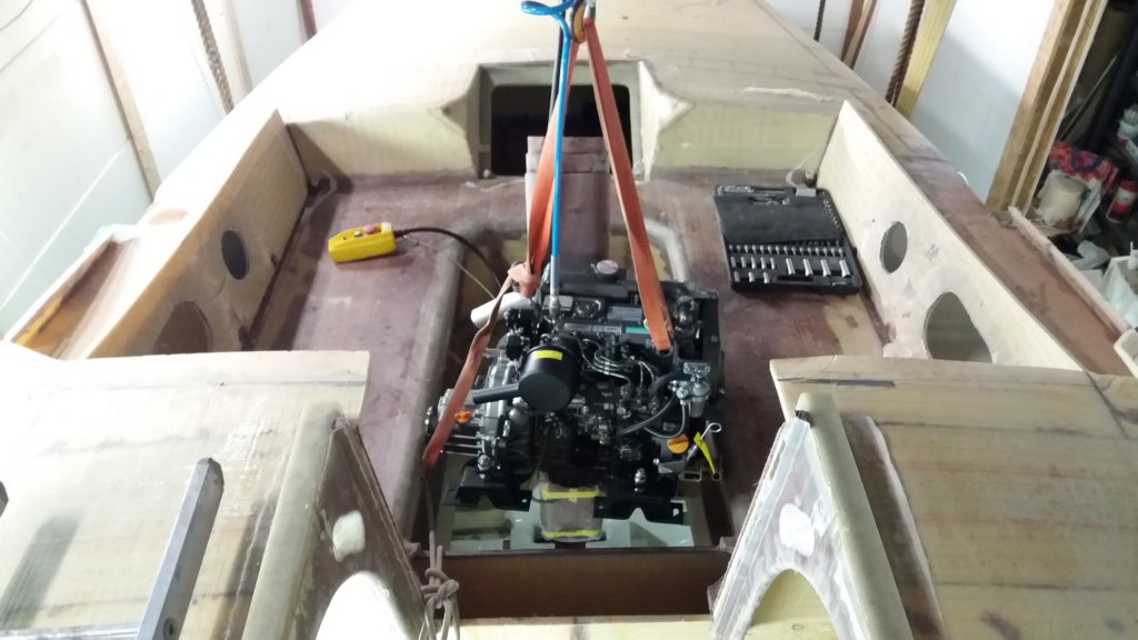
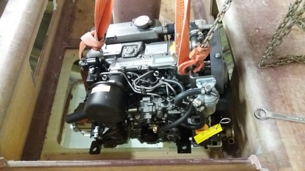
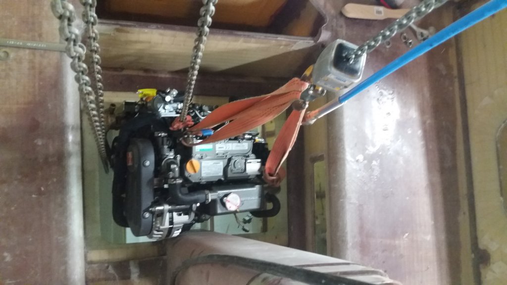
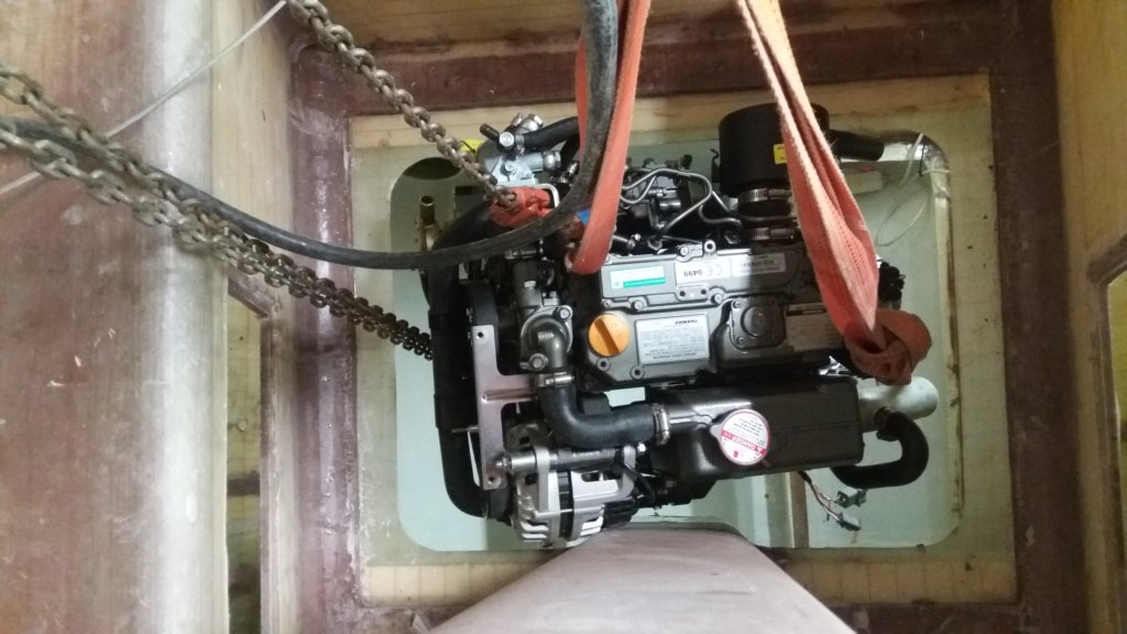
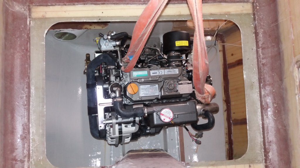
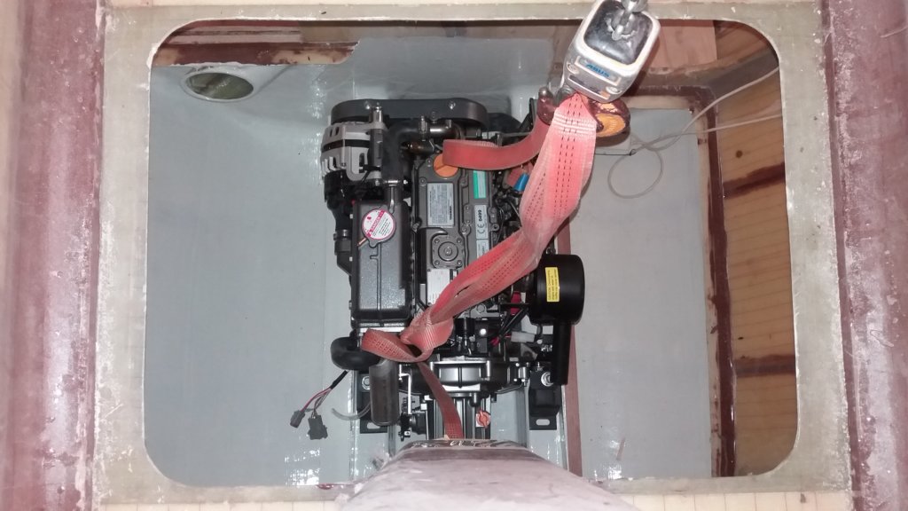
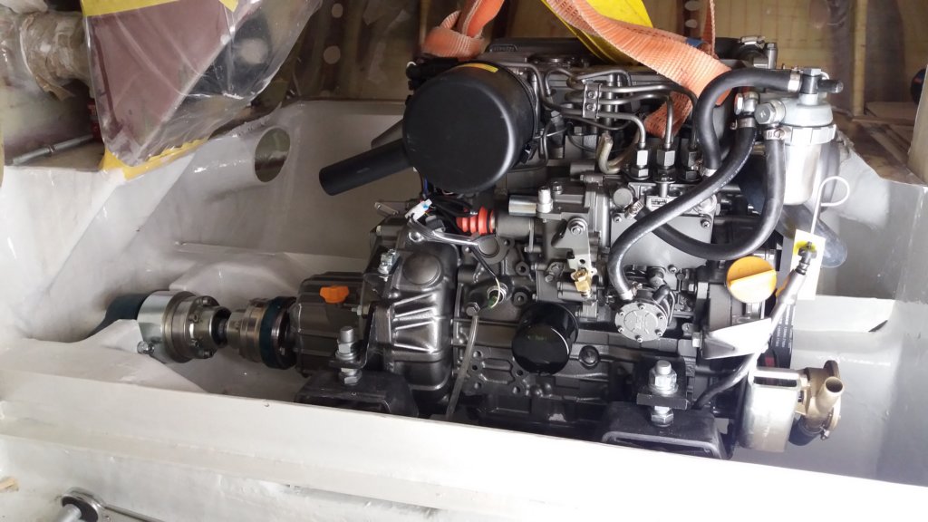
After completing the cockpit structure, I left a temporary opening to lower the diesel engine onto the foundation. Once the engine was in place, this opening was laminated shut again. I deliberately chose not to install a removable hatch, in order to avoid potential leakage and to preserve the stiffness of the cockpit floor. If the engine ever needs to be removed, a new opening can be cut without difficulty.
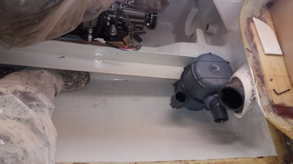
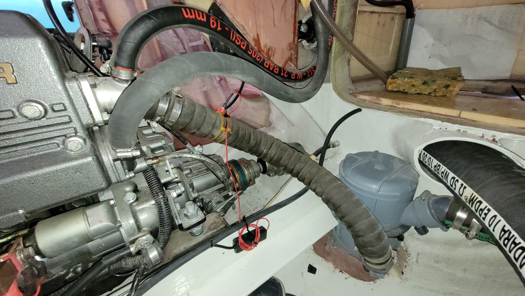
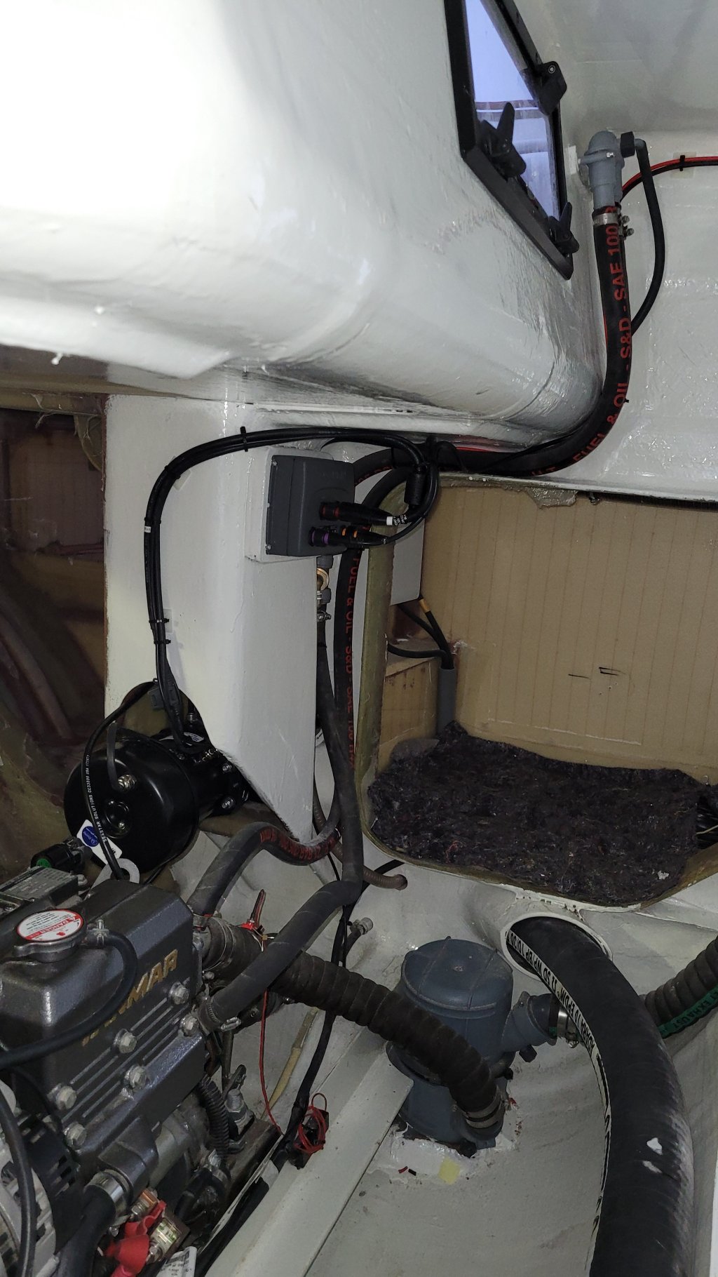
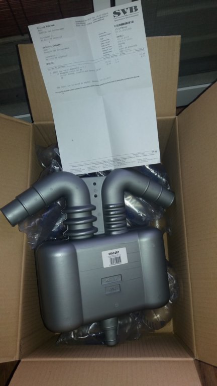
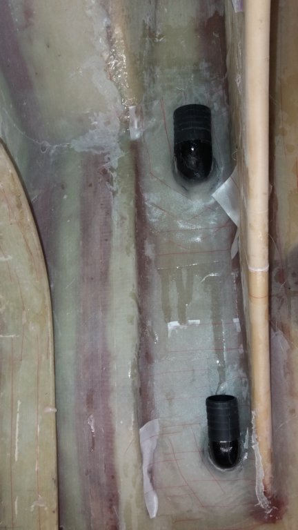
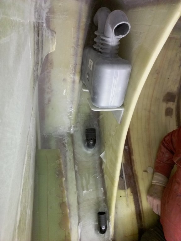
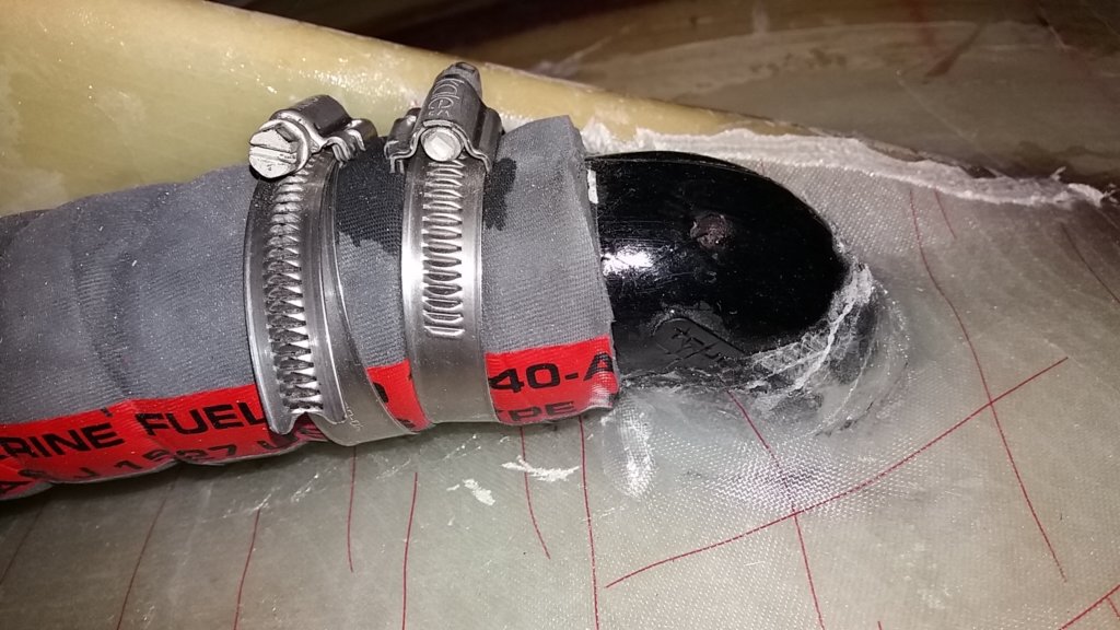
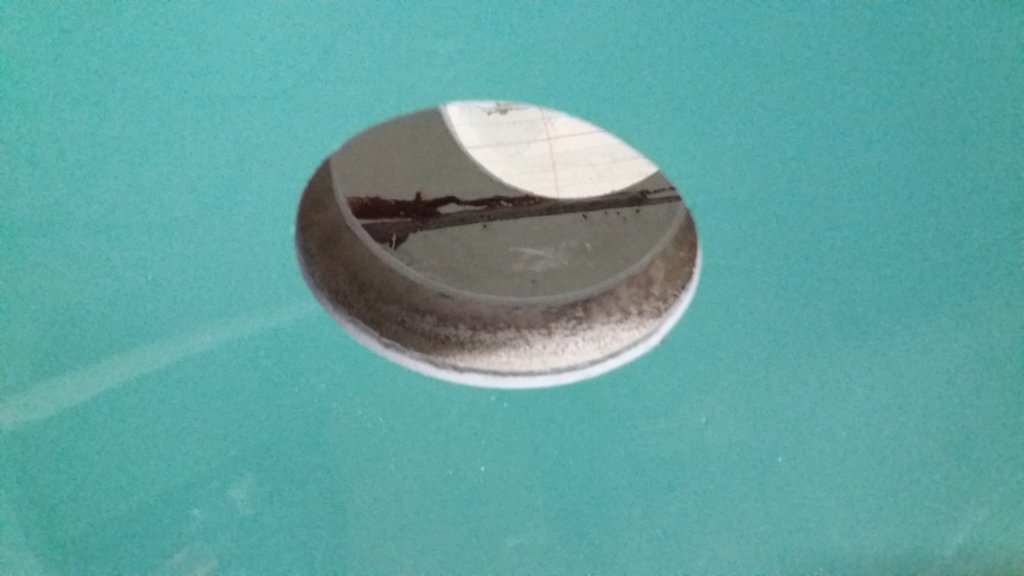
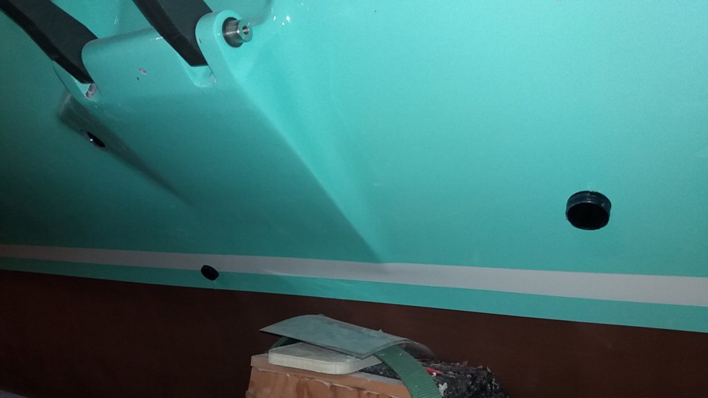
The engine is equipped with a wet exhaust system. Normally, exhaust gases are led through a waterlock and a gooseneck. In this installation, the gooseneck was replaced by a gas/water separator. This unit separates the injected raw cooling water from the exhaust gases and simultaneously functions as a gooseneck. An additional advantage is its excellent sound attenuation, eliminating the typical gurgling exhaust noise. Instead of a single outlet, this system requires two outlets: one for the exhaust gases and one for the cooling water.
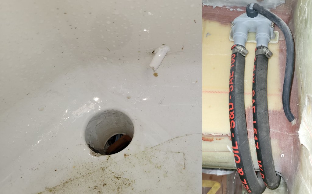
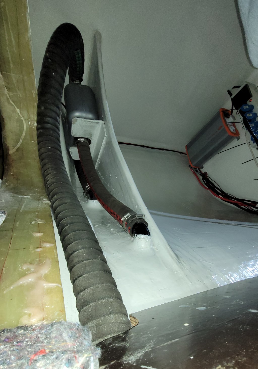
Because the cooling water outlet is located just above the waterline and is visually hidden by the hull shape, and because the gas/water separator makes the system virtually silent, direct visual confirmation of cooling water flow is no longer possible. To compensate for this, a small discharge pipe from the vented loop was routed into the cockpit, just above the cockpit drain. By using a vented loop without a valve, a small amount of cooling water will always be discharged when the engine is running, providing a reliable visual confirmation of proper cooling water circulation.
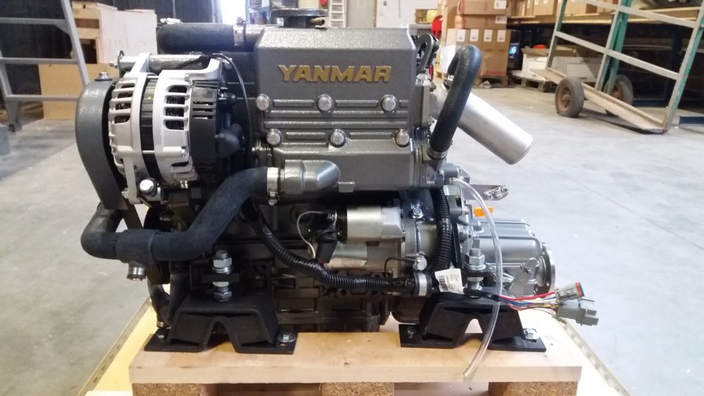
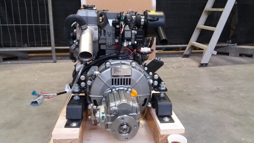
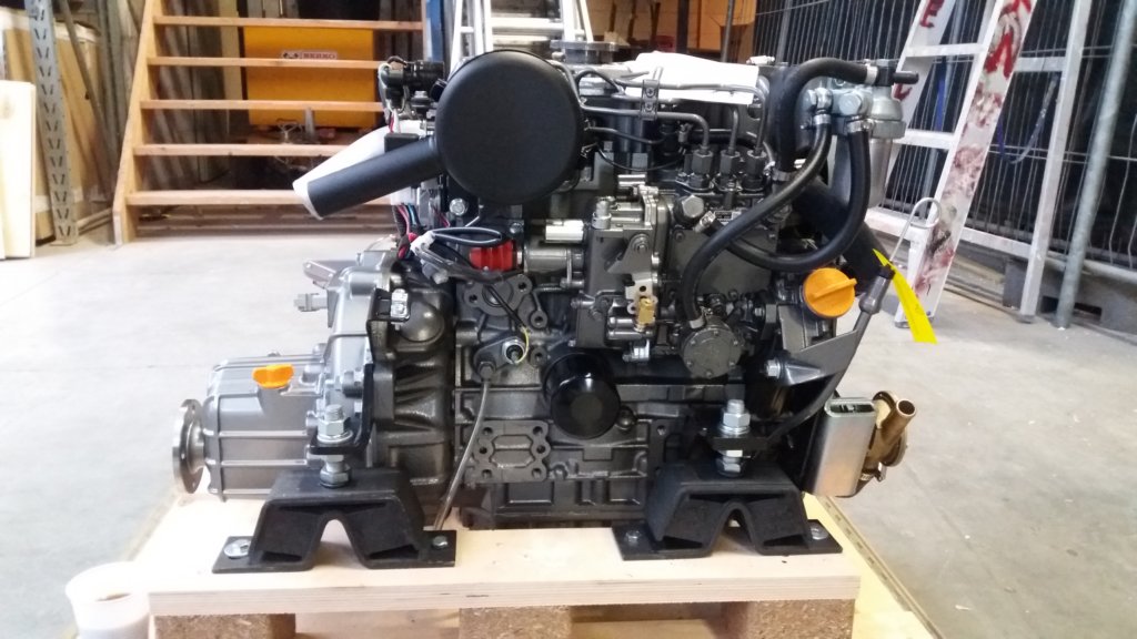
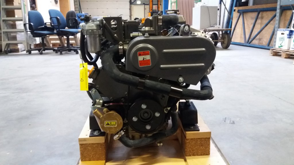
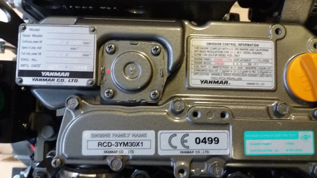
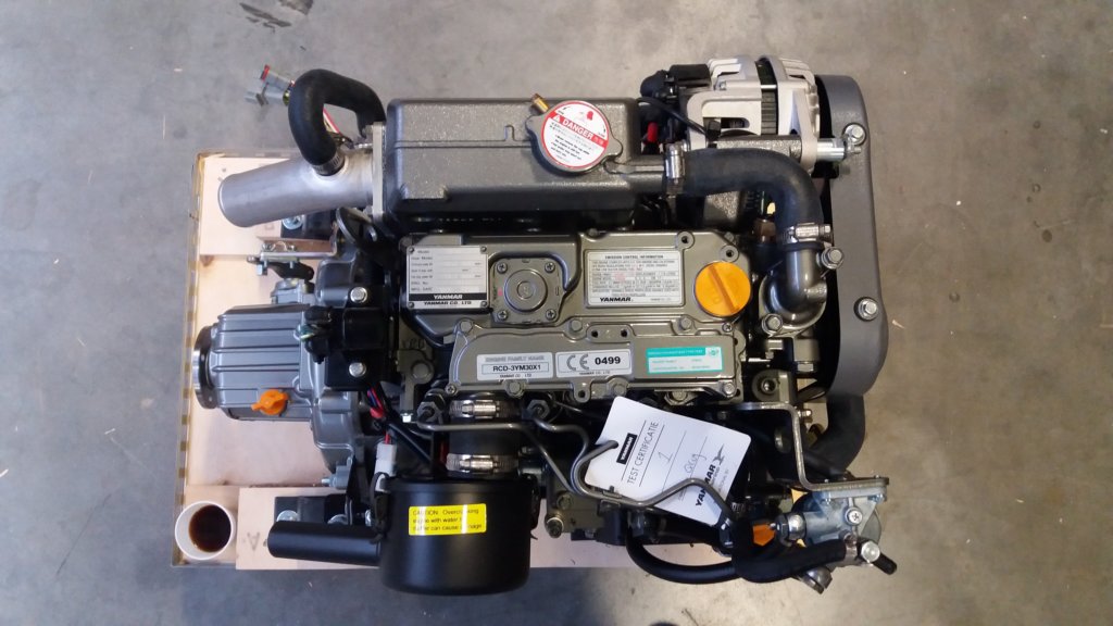
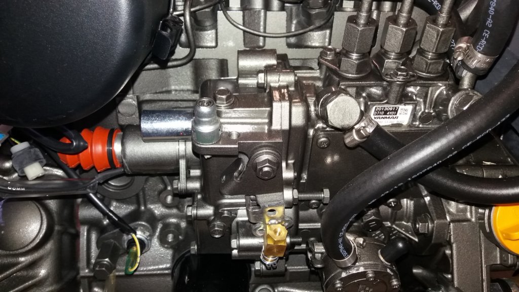
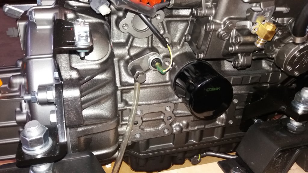
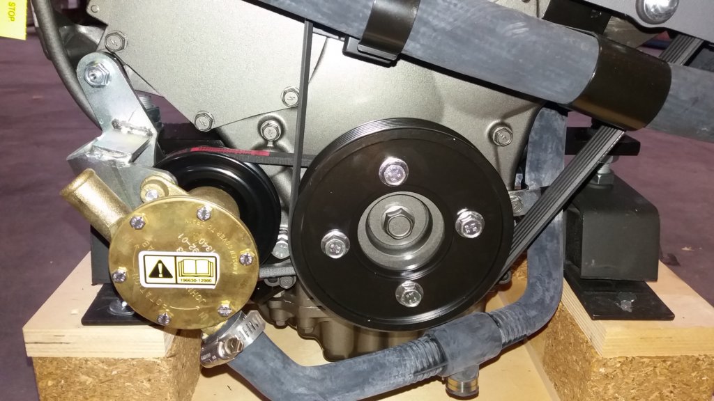
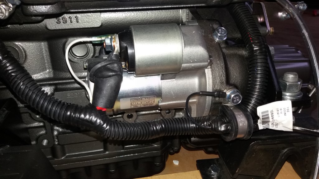
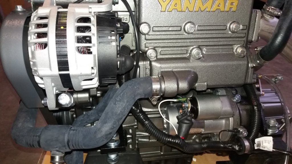
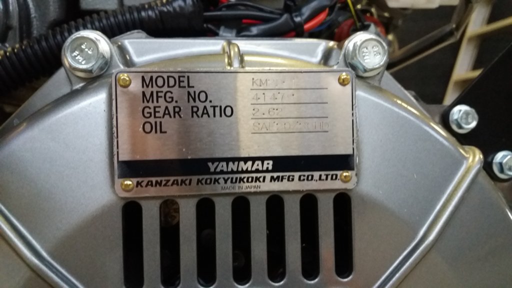
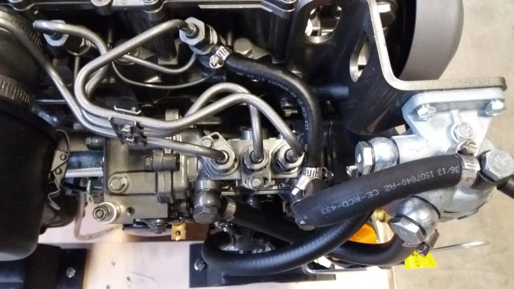
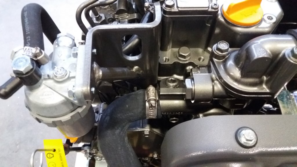
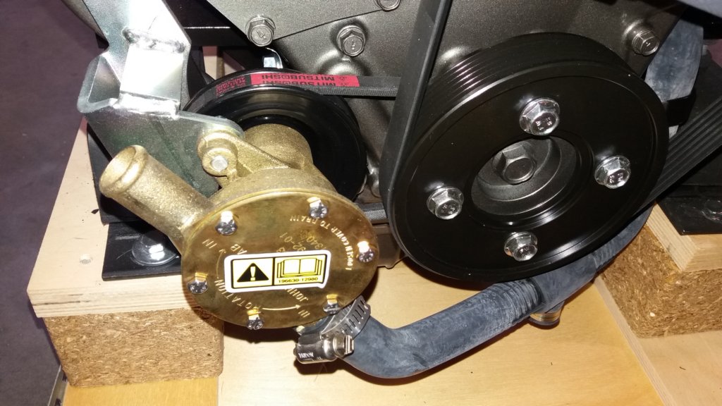
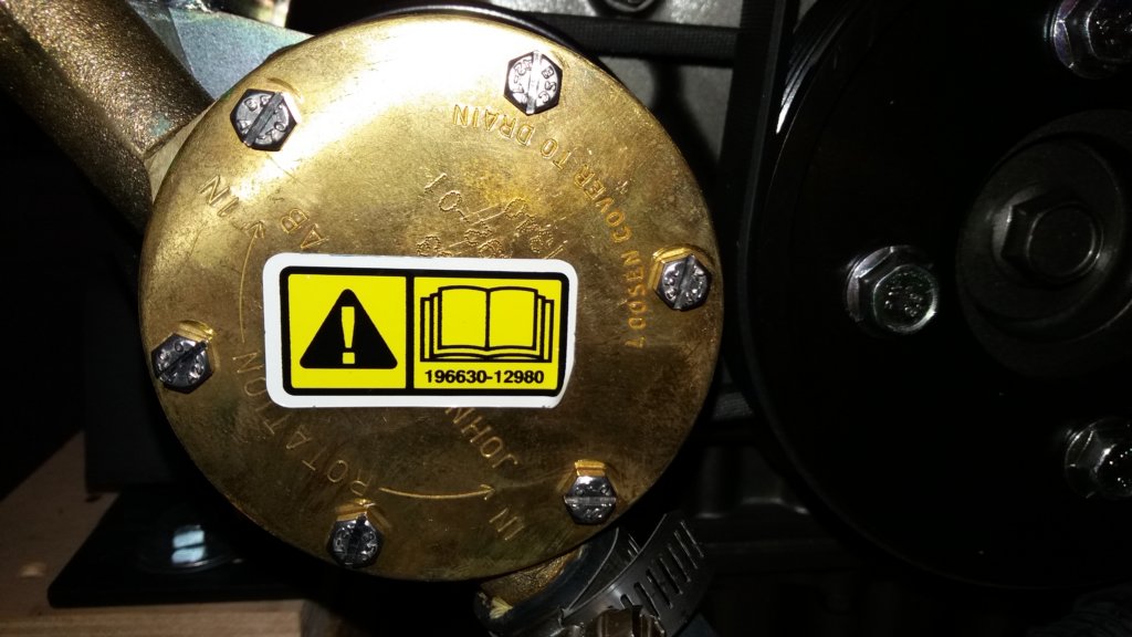
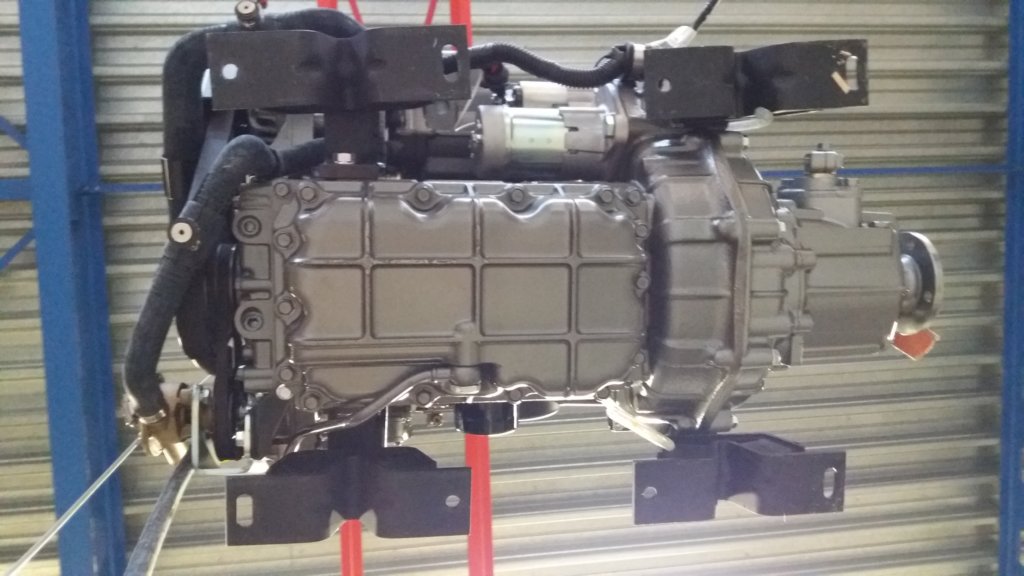
This photo gallery (60 images) documents the complete engine installation, from the construction of the composite engine foundation to the installation of the Yanmar diesel engine, Aquadrive drivetrain and wet exhaust system.
