Fram gets a rotating wing mast. What started as a search for the (now unobtainable) Sparcraft 590C section ended with an unexpected find in the south of France: a Formula 40 wing mast that matches Farrier’s spec remarkably well. This chapter covers the “go/no-go” decision and the full refit list—shortening, stripping, track removal, paint, new sheaves and fittings, mast base work, wiring conduits, and the conversion to modern hardware—before the new carbon spreaders are built in Part 2.
A wing mast for Fram – Part 1
Fram will get a rotating wing mast. Ian Farrier’s construction drawings specify in detail what the aluminium section must comply with. The Sparcraft 590C extrusion comes very close, but unfortunately it is no longer available—unless you order it in truly industrial quantities.
During my preparatory study work I had already mapped out an alternative route: building a carbon mast myself. Yes, primarily for economic reasons—spending €80k (and well beyond) on a production mast was just a bridge too far. So I devised a method for home-building the mast, including a practical way to make the frames and moulds required.
After studying a number of designs, my preference had settled on the Schionning Designs wing mast. It’s a neat concept and, importantly, very well documented—laminate schedules, details, the lot.
But there were still plenty of doubts. All that UD in a mast quickly turns into a low-permeability laminate, which makes vacuum infusion far more complicated than it looks on paper—and it would require extensive testing up front. On top of that, I wasn’t convinced the weight saving would be worth the effort. Realistically, I’d end up “buying certainty” with extra laminate. Prepreg would be the safest method, but that’s outside my practical reach, and it would stretch the build time even further. That last point weighed heavily.
Right at the moment I had to make the go/no-go decision, I got a tip about a wing mast from a Formula 40 catamaran (Data General) in the south of France. In the photos I could see a mast that, at first glance, might actually fit. It was a bit too long, but by cutting off the tapered top everything would fall into place. The (single) spreader was almost exactly where my upper spreader needed to be. The F40 doesn’t have a middle spreader, but that’s where the diamond rigging attaches. At that location there’s transverse internal support: a solid 40 mm aluminium bar through the section—similar to the compression bar used at the upper spreader. Perfect for positioning my middle spreader right there. A consult with a renowned yacht designer and boatbuilder confirmed that, with double spreaders fitted, this mast would meet Ian Farrier’s specifications. I couldn’t ask Ian himself anymore—he had passed away. :(
Given the F40 race circuit (and container transport), the mast is built in two halves. That meant it could be transported on a long rented trailer—still manageable behind a car. All in all, enough reason to drive to the south of France and buy the complete rig: mast, spreaders, boom, and solid rod rigging.
To make the mast and boom fit Fram, the following work was carried out:
- shorten the mast by cutting off the tapered top;
- remove all hardware, except the spreader fittings;
- mill away the original groove/track for sail slugs;
- paint mast and boom in the boat’s colour;
- install PVC conduits for electrical wiring;
- make new hardware based on Farrier’s construction drawings for masthead, mast foot and mast base, fitted with Harken high-load sheaves;
- rework the existing mast foot: clean up, reinforce with a centre web, and fit a pivot ball socket;
- fit new bearings and a new pivot ball for the mast foot;
- fabricate a middle spreader fitting as a copy of the existing upper spreader fitting;
- fit new Antal hardware for fairleads and mast blocks;
- fit a new Spinlock clutch for the gennaker halyard;
- modify the mast for hook-in terminals, turnbuckles and Colligo terminals, plus Cheeky Tangs;
- install a Ronstan mast track for Series 26 Captive Ball Quick-Release Batten Cars;
- equip the masthead with VHF antenna, LCJ-Capteurs ultrasonic wind sensor, and navigation lights;
- build four new carbon spreaders (in the next chapter);
- remove the boom hardware and replace it with new;
- fit a new one-piece CNC-milled boom end fitting;
- fit a new one-piece milled gooseneck fitting for the deck-stepped boom.
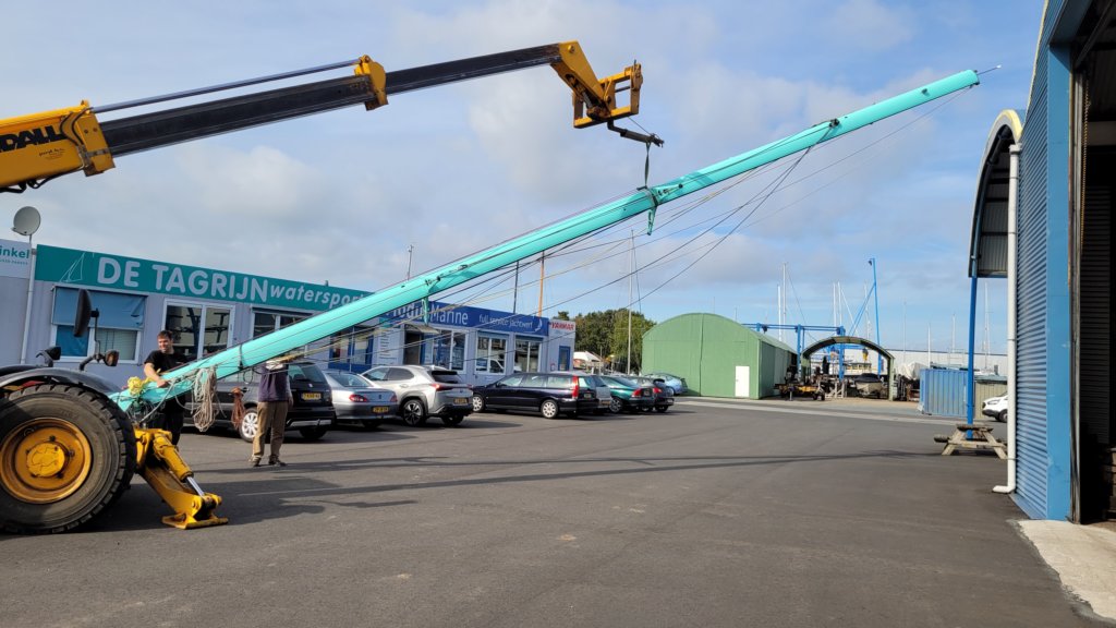
The photos tell the full story.
This photo gallery. shows the complete visual story of the wing mast conversion for Fram: from collecting the Formula 40 mast in southern France, through cutting, stripping, machining, painting and re-rigging, to stepping the finished rotating mast on board. Each image documents a specific decision or construction step, with the captions providing the technical context.
