Rather than installing a ready-made “drop-in” battery, the LiFePo4 service battery on Fram was built from individual cells. This chapter describes the reasoning behind that choice, the testing process, and the final installation of a 24V 300Ah lithium battery system.
Building a LiFePo4 battery
First of all, I should state that I am not an electrician. What I know comes from what I once learned at school in my youth, and much of that knowledge has faded over time. The good news is that, somewhere along the way, I did manage to relearn the difference between volts and amperes.
With that background, I decided to build a LiFePo4 service battery myself. I deliberately did not buy a ready-made LiFePo4 system, often referred to as a “drop-in” battery. By assembling the battery from individual cells, I wanted to better understand the technology and tailor the system precisely to my own requirements.
The concept itself is straightforward. Due to the high power demand of the Jet Thruster on board (11 kW), I wanted a 24 V service battery capable of delivering a continuous discharge rate of 3C (three times its nominal capacity). That is a substantial load and led to a required capacity of 300 Ah at 24 V. This also provides ample capacity for a comfortable onboard electrical system.
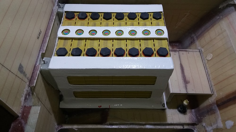
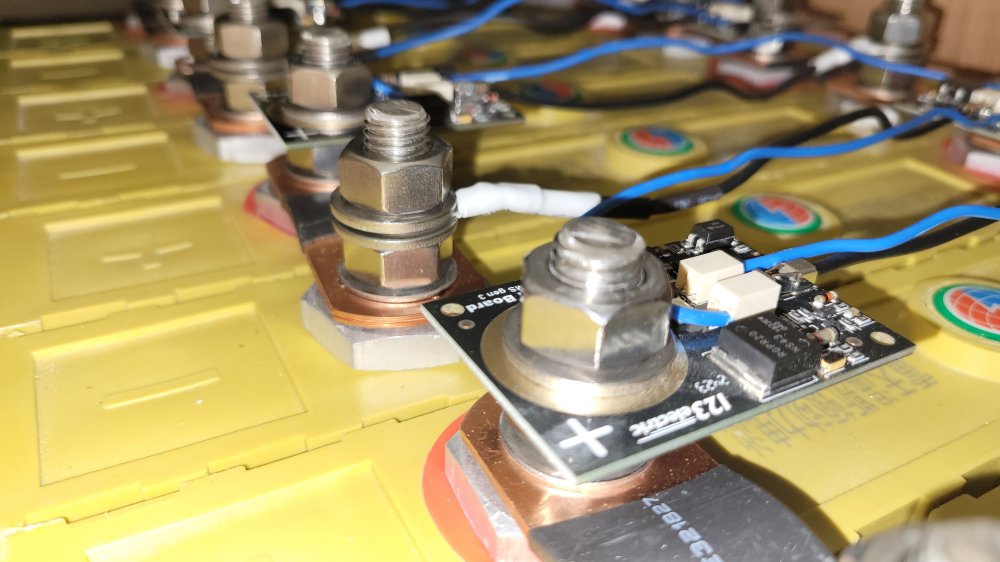
LiFePo4 cells have a nominal voltage of 3.2 V each, so eight cells are required to reach 24 V. Based on these parameters, I selected Winston cells. I purchased them several years ago, at a time when there was limited competition. Today, a wide range of lithium cells is available and prices have dropped significantly.
Many of the currently popular cells, however, are not equivalent in quality or performance. They are often limited to a maximum discharge rate of 0.5C or less, whereas the Winston cells are rated for 3C continuous discharge with peak currents up to 10C. It is no coincidence that these cells still cost a factor of five or more compared to the most common alternatives.
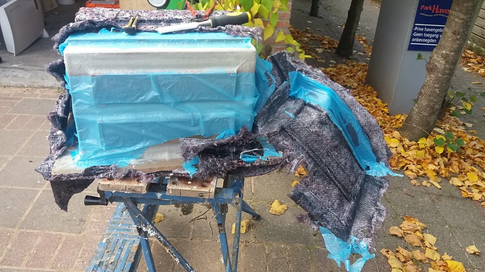
When building the interior, battery placement had to be considered early on, which is why I purchased the cells at an early stage. They then spent several years unused in the garage while other construction priorities took precedence. The intended location for the battery is at the bottom of the dinette crossbench: well protected, close to the boat’s centre of gravity, and—just as important—very close to the Jet Thruster, keeping cable runs as short as possible.
It took some time before I felt motivated to immerse myself in the LiFePo4 world, or as I like to call it, the “LiFePo4 soap.” Forums and YouTube are full of conflicting advice. What one person considers essential, another claims will destroy your battery. Even suppliers contradict each other. It is easy to lose sight of the fundamentals. In the end, I distilled a few clear and manageable principles for myself:
• Initial charging to a maximum of 3.65 V per cell (although the manufacturer specifies up to 4 V);
• Installation of a BMS (Battery Monitoring System) to monitor individual cells—mainly for peace of mind;
• A maximum total charge voltage of 27.6 V for the entire battery;
• No trickle charging: charging stops at 0 A once fully charged;
• Protection against deep discharge;
• No charging at freezing temperatures (despite Winston stating this is permissible);
• For longevity, avoid storing the battery fully charged when not in use;
• A DC–DC charger between the engine start battery and the LiFePo4 battery, powered by the engine alternator.
The DC–DC charger primarily serves to protect the engine alternator from overload. In my case, it also converts the alternator’s 12 V output to the required 24 V (27.6 V charging voltage). Additionally, a conventional start battery remains in the system to ensure the alternator always sees a stable load, even if the LiFePo4 BMS were to disconnect charging.
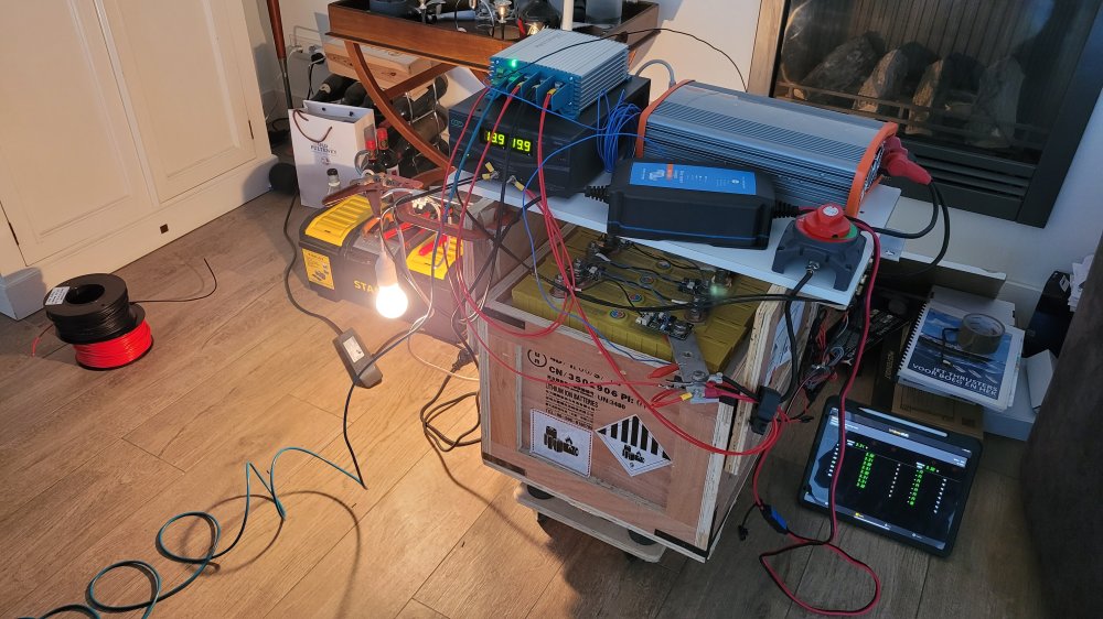
To better understand the system and gain practical experience, I assembled a full test setup in the living room. This replicated the intended onboard installation. The engine alternator was simulated using a laboratory power supply, while the load was represented by a 100 W light bulb powered via a 230 V inverter. With a computer connected to the DC–DC charger, I was able to monitor and vary the system parameters.
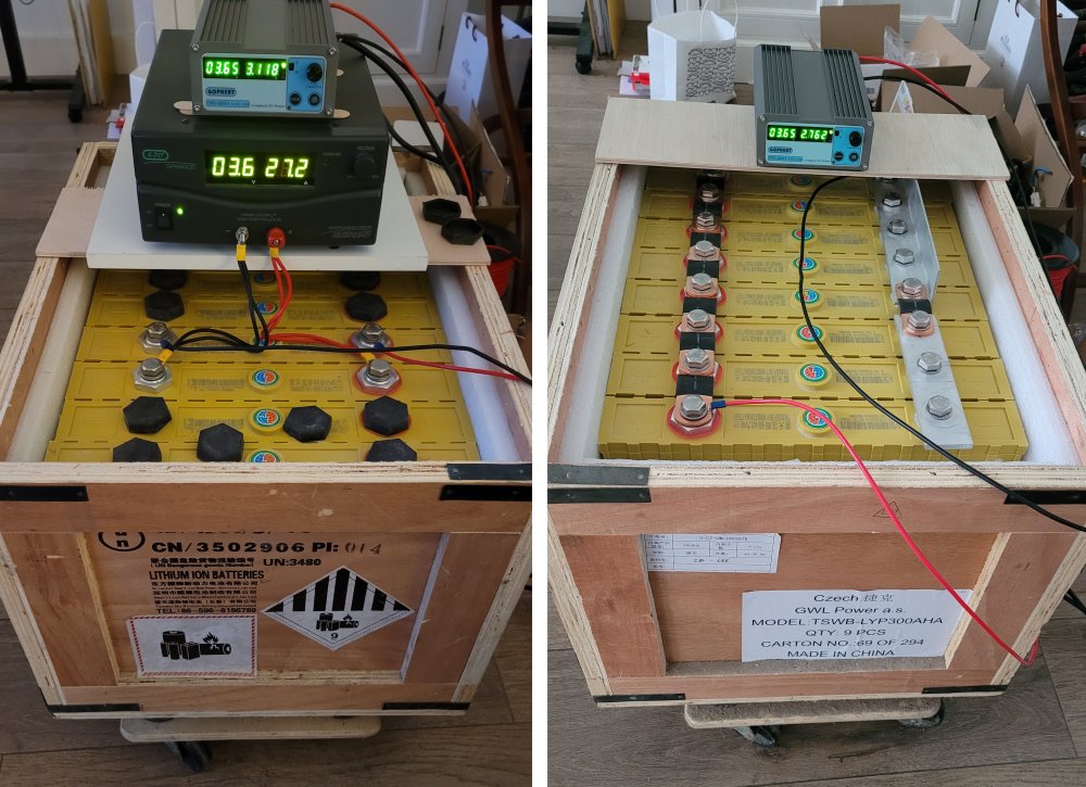
The first step was the initial charging of the cells. The eight cells have consecutive serial numbers and originate from the same production batch. All arrived from the factory at approximately 3.28 V. Using a laboratory power supply, I charged each cell individually to 3.65 V. This process took about a week, with charging paused overnight. The cells were then connected in parallel, forming a single 3.2 V, 2400 Ah battery, and charged again to 3.65 V—a process that took only about ten minutes. After a short rest period, the cells were finally connected in series to form the 24 V, 300 Ah battery.
The amount of energy stored in these cells is remarkable. To avoid accidents, short circuits must be prevented at all times. Knowing my own tendency to be a bit too casual, I purchased an insulated wrench for tightening the M12 terminal studs.
With the battery assembled, the setup was completed with chargers, converters and loads. I spent roughly three months experimenting with different configurations and settings, keeping the system almost continuously in sight in the living room.
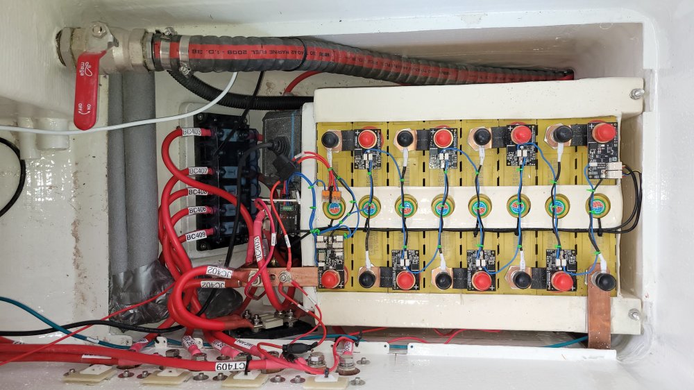
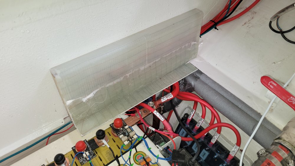
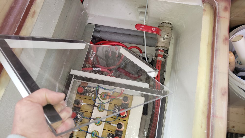
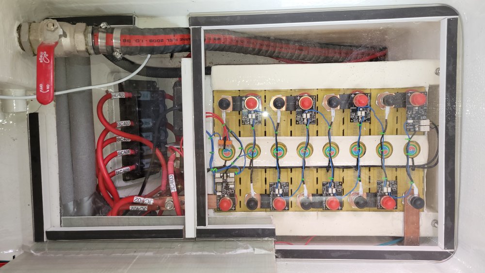
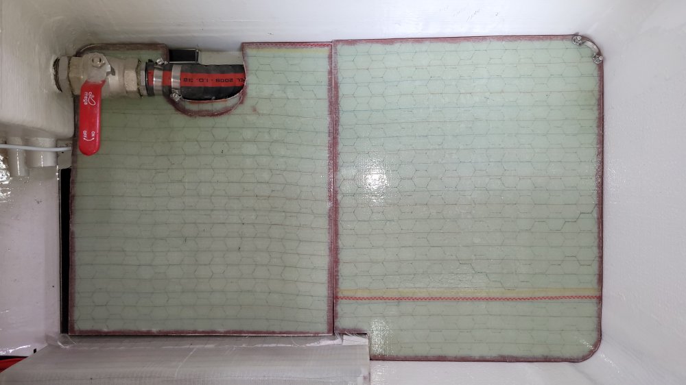
Once I felt confident that I understood both the behaviour of the system and the measures required to keep it operating safely, the test setup was dismantled and installed on board. The battery is now located at the bottom of the dinette crossbench, fully protected beneath a removable floor. This space also remains perfectly usable for storing supplies.
This photo gallery of approximately twenty images shows the successive steps in building and installing the LiFePo4 battery.
